Thursday, December 28, 2017

uBITX TFT display update 1/10/2018

I had a little time over Christmas weekend while everyone else was watching football to work on the TFT display for the uBITX.  I grabbed a 2.4" TFT display from another project and connected it to the Nano I am using as a test bed.  Just to be sure about the logic levels the display wanted I fed the control lines through a voltage divider made up of a 4K7 and 10K resistors.  This display gave me a much larger area to work with, and I could add some of the features that several other people suggested.  One of them was the display of the A: and B: VFO frequencies.   I decided to display the active VFO frequency in a larger font, with the alternate in a smaller font and a different color. 


 Another suggestion I uses was, when the RIT function was active, I displayed the offset from the transmit frequency.  I also changed the RIT tuning steps to 50 Hz. instead of 100.  I still have several other settings I need to display on the screen, but it is starting to take shape.


One other thing I wanted to do was add was an analog meter.  Mainly to use as a s-meter, but possibly as a power meter that will switch between modes on receive or transmit.  I looked at and tried the code from several versions I found, but they were fairly large in code size and required quite a bit of processing to compute the needle movement.  I decided I wanted top try something a little simpler.  Instead of using sin and cos functions to compute the angular position of the needle, I would treat  everything as a straight line value.  This lets me just draw a line from a pivot point for the needle to some point near the top of the meter face.  The line length would vary, but the effect would look close enough to an actual meter.  This resulted in two very simple functions, one to draw the meter itself and the other to plot the needle.  To move the needle, first it is drawn in the face color of the meter to erase the old value and then redrawn in the desired needle color.
The function to draw the meter is very simple 


void drawMeter(int x, int y, int w, int h, int face_c, int bar_c, char *txt) {
  tft.fillRoundRect(x, y, w, h, 5, face_c);
  tft.fillRoundRect(x + 1, y + 1, w - 2, h / 5, 3, bar_c);
  tft.drawRoundRect(x, y, w, h, 5, YELLOW);
  tft.setTextSize(1);
  tft.setTextColor(YELLOW);
  tft.setCursor(x + 2, (y + (h/5))-12);
  tft.print(txt);
}

Draw a  filled rectangle with rounded corners at the desired position and size, then draw another that will serve as the background color for the meter scale.  I also added another empty rectangle around the main one to highlight the meter.  Then position the cursor and print the meter scale.  I did not add auto sizing of the meter, so the actual size of the main rectangle, will have to be determined manually from the desired text on the meter scale.  To draw the basic meter without needle is to give it a position, size , colors needed, and scale text.

// define some values for the meter position and size
#define  MTR_X   160
#define  MTR_Y   108
#define  MTR_W   155

#define  MTR_H   100

drawMeter(MTR_X, MTR_Y, MTR_W, MTR_H, WHITE, RED,"0  2  4  6  9 +20 +40 +60");


Plotting the needle was simpler than I had expected.  Since I was treating the meter range as a straight line value.  I pass the function the same parameters for position and size as the drawMeter function, and add the value, max_value and color to draw the needle.  
void plotNeedle(int x, int y, int w, int h, int value,int max_value,int color)
{
  int tw;
  int w2 = w/2;
  tw = map(value, 0, max_value, 3, w-3 );
  tft.drawLine(x + w2 ,   y + h - 4,  x+tw ,    y + (h / 5)+4, color);
  tft.drawLine(x + w2+1,  y + h - 4,  x+tw+1  ,  y + (h / 5)+4, color);
  tft.drawLine(x + w2+2,  y + h - 4,  x+tw +2 , y + (h / 5)+4, color);
}
Then I used the Arduino map() function to return a value that represented the position along the meter scale based on the value read and the maximum value.  Then just plot a straight line from the pivot point for the needle to just below the meter scale, which I compute depending on scale size.  I draw this three times with a slight offset to make the needle more visible as it moves. 


Since the only available Analog pin is A7, wrote a little code to read that value and display the meter reading. 
  meter_reading=analogRead(A7)/2;
  plotNeedle(MTR_X, MTR_Y, MTR_W, MTR_H,last_meter,1023,WHITE);
  plotNeedle(MTR_X, MTR_Y, MTR_W, 1MTR_H,meter_reading,1023,BLACK);
  last_meter=meter_reading;

Next I will see about building something to get a signal from the uBITX to display.  I might start with a simple voltage doubler off the top of the volume control just to see how well it works.  Later I will probably tap into the IF chain to get an actual S-Meter .  Also thinking about adding a pickup off the antenna lead to measure power output, I can probably use the PTT signal to allow switching between meter readings from receive to transmit.

Update 1/10/2018

After playing around with several different versions of the display screen, I have come up with something I like.  Following a couple of suggestions from N6QW, I now show options available in Cyan and any active settings in Yellow.  On the screen you can see the second VFO frequency, and that RIT is optional.   

Below the frequency read out, I have an area to display the command prompts from the uBITX, such as band change, VFO selection, RIT on/off. 


When RIT is turned on the offset from transmit frequency is displayed. I did make a change to the original code to change in 50 Hz. steps instead of 100 Hz.  


Finally I added a transmit indicator, and also checked the CW keying line and changed the mode display while a keying is present.

I am happy with the way the display looks, now to put everything in a box and see how it works.  I think I will re-write the code I have for the BITX40 and use one of the VFO/BFO boards I designed.  With that I have more Analog input pins available and should be able to implement power and SWR readings on the screen.


UPDATE 1/29/18 

I have received several questions about the display I used on my uBIX.  The ones that I am most interested in are the ones that use a  ILI9340 or ILI9341 controller.   They are available in 2.4" or 2.8 " models.  I have found the response to be very fast using the standard SPI interface.  


The main issue with them is that they usually require 3.3 volt logic levels instead of the 5 volt from Arduino, I have found a simple voltage divider does well in this application.  I usually power the LED pin through a 100 ohm resistor to 5V.  If a PWM pin was available, I would add backlight intensity control instead.  Software changes in the main sketch  ubitx_20 were fairly simple, and then I replaced the ubitx_ui  file with a modified ubitx_tft_ui file.  Changes to the ubitx_20 file are made in the declarations 

/*
Comment out the original display driver  and replace with the Adafruit drivers
#include <LiquidCrystal.h>
  LiquidCrystal lcd(8,9,10,11,12,13);
/*

// WE ARE GOING TO USE A TFT DISPLAY

#include <Adafruit_GFX.h>
#include "Adafruit_ILI9340.h"
#define _sclk 13
#define _miso 12
#define _mosi 11
#define _cs 8
#define _dc 10
#define _rst 9

#define CALLSIGN  "KV4QB"

// Color definitions
#define BLACK   0x0000
#define BLUE    0x001F
#define GRAY    0x3333
#define RED     0xF800
#define GREEN   0x07E0
#define CYAN    0x07FF
#define MAGENTA 0xF81F
#define YELLOW  0xFFE0
#define WHITE   0xFFF6

Adafruit_ILI9340 tft = Adafruit_ILI9340(_cs, _dc, _rst);

and then in the setup code make these changes
  // lcd.begin(16, 2);   // using tft instead of lcd

  // setup the tft display and draw basic display screen
  tft.begin();
  //tft.initR(INITR_BLACKTAB);  //ST7735 depends on exact one used
  tft.setRotation(1); // landsacape versus portrait

  tft.fillScreen(BLUE);

  //we print this line so this shows up even if the raduino
  //crashes later in the code

  printLine1("uBITX v0.20");

  tft.setTextSize(3);
  tft.setTextColor(YELLOW, BLUE);
  tft.setCursor(22, 20);
  tft.print("uBITX v0.20");
  delay(1500);
  tft.setCursor(22, 20);
  tft.print("           ");
    drawDisplay();

With the updated ubitx_tft_ui code I tried to keep the code in the other files as unchanged as possible.  Except for the display, nothing else has been changed.

Here is a link to my modified uBITX sketch to support a TFT display instead of the normal 2 line LCD display.  Hardware change  is a small board with the voltage dividers that has a connector for the TFT display.  Only the first 8 pins are used.  Then there is a short cable that plugs in where the existing display plugs in on the Raduino board.

https://www.dropbox.com/sh/hhqxprggo9rct3v/AACrI9ceAKDYNnFPBH29Ig5ta?dl=0


Sunday, December 17, 2017

Santa Came Early - uBITX update 12/20/17/.........

I had not realized that Santa traded in his Sleigh for a yellow cargo van, but he must have.  After seeing that the new uBitx was available for sale last Saturday, I thought about ordering it.  Then about 2 AM Sunday morning I couldn't resist much more and pushed the button at Paypal.  

Just sitting around Thursday afternoon when the door bell rang, and there disguised as a DHL deliver driver was Santa.  I couldn't wait to see what the new toy looked like.  So after letting Santa get on his way to his next delivery, I tore into the box.  Inside the sturdy cardboard box was a plastic box with a couple of bubble wrapped boards, and a bag of parts. The uBitx board and Raduino are each wrapped in bubble wrap, and I could not see any shipping damage on either one. 

 I plan on replacing the 2 x 16 LCD display with a small TFT display, so I took a look at the wiring diagram of the display connector.  I checked the pins and they contain all pins to use hardware SPI on the Arduino to drive a TFT display.  I wired up a 1.8" display I had from other projects, and could not get it working with the pin combination I choose.  Playing around with some other wiring combinations, I was able to get it working.  Still wondering about that, because I have always been able to map anything but 11 and 13 to anything I wanted to use.  I realized that pin 12 is also used by the hardware SPI, and after changing to pin 10 everything worked as expected.  First thing I had to do was disable the LCD driver software and include the Adafruit libraries for the ST7735 and the graphics routines.  After that I replaced the LCD display routines with ones written for TFT display.  Luckily the uBITX routines map everything related to the display to a couple of simple functions.  It took very little to change these over to the TFT display.  
The only problem I found was that with the 1.8" display I only had a x resolution of 160 pixels, and that limited me to using a small size font, without the text wrapping around to the next line.  But everything should work after I redesign a display screen layout to replace the default two line layout used in the stock uBitx.  The 1.8" display could be wired in directly, but for a 2.4" or 2.8" I will need to converted from 5 to 3.3 volts on the control lines.  I have found that simple voltage dividers work well for this, as the data flow is only one way.  At last something to keep me busy for the holidays


UPDATE 12/20/17
To make things a little easier to work with on converting the uBITX display to a TFT display, I wired up a Nano, display, encoder, and a couple other parts on a wireless breadboard.  This will allow me to take everything along when I go to spend the holidays with relatives.  So far it has been fairly easy to come up with a screen layout that fits well on the 1.8" display.  I am trying to limit any code changes to the ubitx_ui module, and mainly to the updateDisplay() function.  This should make it possible to easily switch back to the LCD by just loading in  a different version of  the ubitx_ui module, or possibly use  of #ifdef depending on how complicated the whole thing turns out.
With the limited size on the 1.8" display I am trying to keep everything as simple as possible.  It looks like I will probably have to switch toa separate screen display when I switch to setup mode.  When I move to a 2.4" or 2.8" with higher resolution, I will have room for information to be displayed at one time, and may be able to add a pop-up sub menu. 

As of now I have the FREQUENCY, VFO, and MODE display finished.  Just now trying to add the RIT status display to the empty red box on the right of the screen.  Also plan on having the command prompts from pushbutton work as a pop-up item. Don't know how much I will get done before I have to pack it up and go visit relatives, but will keep you informed.

Thursday, November 30, 2017

CNC Engraver update 12/6/17


I had been planning on doing a update on the CNC Engraver purchased to use as a PCB mill, but a couple things have gotten in the way.  First is the series articles I am writing for QQ, the designing, building, and testing, along with the writing is taking quite a bit of time.  Second reason was that I was clumsy. I had the unit along with power supply and cables all wrapped up and out of the way, I thought.  Then I was moving something else and knocked the power supply off the bench.  Of course it was wrapped with the USB cable, so when it fell it tore the USB connector off the controller board.  I tried to repair the board, but too many of the traces wore gone.  I had to order a replacement board, which has now brought the price up to what it would have been if not on sale when I got it.  While I was waiting for the replacement I designed and 3D printed several things to prevent this from happening again.  I made a cover for the circuit board, and some brackets to hold the power brick in place.  Along with the new controller board, I also ordered a Panel mount USB to mini USB cable.  I printed a bracket for it and some cable management clips that fit in the 2020 aluminum extrusion that makes up the frame of the engraver.  After everything arrived, and I finished printing the parts, everything looks really nice and secure mounted on the frame.     


The first picture is of the back with the cover for the circuit board, including a cooling fan for the stepper drivers.      
A set of brackets to hold the power brick and the bracket for the panel mount USB connector.  

Next is a picture from the front showing some of the board and work piece holders I also printed.  The slots in the aluminum frame of the engraver work really well for storing accessories and work piece holders.

Along with the the repair and modification of the engraver itself, I have been spending quite a bit of time trying several different CNC  software packages.  And breaking quite a few engraver bits along the way.  To make things more interesting, I also changed my PCB design software.  I had been using the free version of Eagle, but the latest version reduces the size of board you can produce.  I looked around and found Sprint Layout, it is not free but only costs around $50.  I tried the demo version before I purchased, and found it to be one of the easiest to learn of all the different packages I had tried.  It allows you to generate Gerber files for sending to board houses, if I want to have boards made.  I can also print normal or mirrored images of the copper layer for making my own boards by 'toner transfer'.  One other thing I really like, is that I can make a complete assembly such as a bidirectional amplifier or mixer stage a single component that can be dropped onto a new board layout.  I can see where this could make several projects I am working on much easier to lay out.
With all that I finally managed to route a complete circuit board.  I think I could do a much nicer job using 'toner transfer' , but it is a start.  I will play around some more tweaking settings in the various software packages I need to use to do the entire process.  One thing I did was to make a drill file for a board I had etched previously, and it did a nice job of drilling all the holes.  I may end up routing the boards for larger less crowded projects and etching the board, using toner transfer for more dense projects. Then just use the engraver for drilling all the holes and trimming the board. That has always been the most time consuming part of making fairly complicated boards with through hole components.  And a real pain to get the alignment correct on double row header connectors.  Well still have a few engraving bits left so will have to see what I decide on doing.  

12/6/17  
I bought a 3 lb. box of scrap pcb  material on eBay to use to play with the engraver as a pcb mill.  Was pleasantly surprised that most of the material was around 4"x6" double sided and in thicknesses from about .020" to .063".  A better deal than I had buying specific sizes in the past.  
With that I spent some time playing with the software packages I need to design and mill the boards.  First, since I switched from 
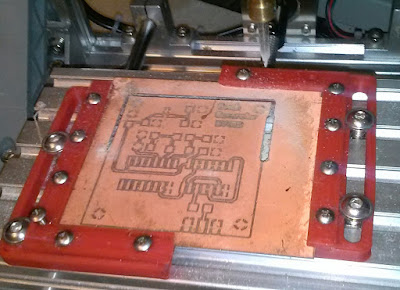
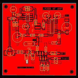
Eagle to |Sprint Layout, I had to play with some of the settings  to get the correct clearance around traces and pads.  Milling the boards seem to make that dimension a little more critical than when I etch the boards.  After getting those settings adjusted and exporting some Gerber files, next I had to work on some settings and sequence of steps I use in FlatCAM to generate the g-Code for the engraver.  Finally I built and installed a Z-axis zero probe to help adjust the Z height of the router bits in relation to the top of the pcb material.  With these settings modified, I decided to try a couple different boards.  The first was converting the LC380 amplifier board from the simpleceiver to Sprint Layout format.  This went quite well after just a little playing with the software. After using FlatCam to generate the g-Code and then making the adjustments for X,Y and Z zero in the GRBLcontrol software I use to control the engraver I milled a board. 

 I was very happy with the results, everything was nice and clear.  It did not look like there were any problems with uneven milling due to the pcb material not being level.  I was worried about that, and had another auto-leveling program I could use if needed. But everything turned out great.  The next thing I wanted to try was a SMD board with size 805 components.  I took the AD8307 power meter circuit I had used on several projects, and changed  the components from 1206 to 805 size.  After generating the g-Code and milling the board I was more than pleased with the results.  

Everything was nice and sharp, no problems with under or over milling around the pads on the SOIC 8 AD8307 or any of the other components.  The only problem was getting a decent picture of the completed board. 

I am now very pleased with the results I can get milling PC boards on the small engraver.  It is small enough and sits right next to my computer desk.  Now I can design, layout and mill a board with out having to even get up from the desk.


Saturday, October 28, 2017

AD8307 power meter QQ article additional build notes update 11/12/17


I just received the latest issue of QRP Quarterly with the first in a series of articles I am writing on using a building block approach for designing and building simple Arduino based test equipment. These articles mostly cover projects I have previously featured in my blog posts, and that I have received requests for additional information on.  I am going to post additional build information on this blog, and in a dropbox folder listed in the article. 

https://www.dropbox.com/sh/ooubfjxdvjao8by/AABe6N-vTZjaMSgUAG0jeGSca?dl=0

 I will be making available the sketch, along with the Cad and Gerber files for the circuit boards. I will also have .PDF files of the copper layers that can be used to make your own boards using the "toner transfer".  For those who do not want to make their own boards, I have a limited number available that I will mail to US locations, contact me directly at duwayne@kv4qb.us for pricing.  For those who would like to order multiple boards  or are outside of the US I have created a shared project at PCBWay.com.  The direct URL for the project is  https://www.pcbway.com/project/shareproject/W42368ASJ6_as8307_pwr_meter_brd__V_2.html 
 They have very reasonable prices for boards this size, and offer several methods of shipping depending on how quickly you want them.  Using HK post I usually get the boards in between two to three weeks, DHL gets them to you in less than a week but is more expensive.


Updated Arduino Display building block
A couple notes on the Arduino display building block.  When  I did a revised board layout to make it easier to use with a 3D printed case,there were a couple changes that are different from the schematic in the article.  The only display pins that must be connected to a specific Arduino output line are CLK (13), and SDA(11),  All  the other pins can be connected to any other Arduino outputs, as long as they are defined in the sketch.  I have moved the LED on the display to pin 9 on the Arduino.  This is a PWM pin and can be used to control the display brightness if desired. If you use this option, you can change the value of R1 to a smaller value such as 47R.  On the probe style board I used pin 7 instead of 9 to make layout a little easier.
R2 and R3 are a voltage divider used to measure the supply voltage.  The values are chosen to minimize current usage, and the values used must be defined in the sketch to correctly calculate the supply voltage input to the Arduino.  The board also has  provision for a optional reverse voltage diode.  If used uncomment the line of code in the sketch that adds this to the measured value.  The .7 volts is probably close enough to use, but you could measure the voltage drop across it and use that value instead.

Looking at the schematic for the AD8307 log amp, you will see that I use small molded RF chokes for connections to the Arduino.  In most circuits I have seen a small value resistor,  usually around 4.7 to 10 ohms is used instead.  I found that since I am using the 5 volt output of the Arduino to power both the AD8307 and the TFT display, I could get a lower noise floor with the RF chokes.  You could use the resistor instead if you want. Also when I did the board layout I only put in one 100nF bypass capacitor on the AD8307.  With good shielding of the AD8307 circuitry it did not make any difference I could see.

Here are larger parts placement diagrams for the top and bottom of the boards. 


Notice that I install all the through hole components on the bottom side of the board.  This allows the Arduino pro-mini to be installed in a 24 pin low profile IC socket if desired.  If you do I have found it works better to install the longer header strip pins  down through the Arduino and then clip off the shorter pins on top of the header strip.
 I usually just solder it to the board without a socket instead.

The placement of  SMD parts on the top layer for the AD8307 circuitry is the same for both the Probe  and  Altoids tin style boards.

 I hope to add some additional notes on the software later this weekend.

UPDATE 11/12/17

I have been fighting the small 1.44" 128x128 TFT display used in this project.  Received a order I had placed a while ago, and the ones I received were a different revision than I had used before.  I know there were two different versions and had the sketches setup so I could use either version.  Now there is another new version and I can not get it working with either version of driver I had used before.  I have tried several different configurations with no success.  Along the way I found a Arduino forum that covers this type display
 https://forum.arduino.cc/index.php?topic=260605.0
It seems like there are more than a few problems with some of the newer versions.  I think I will switch over to the 1.8" display I used in my SNA Jr. instead.  Slightly larger, but I think it will fit in the same size case. I have only found one set of drivers for it, and that might eliminate some of the problems that have been reported with the 1.44" display.
Have a couple on order and when they get here I will rewrite the sketch to reflect the changes.


Tuesday, September 26, 2017

A Two Channel SI5351 Signal Generator Update 9/28 9/30/17

After getting the sketches written for the SI5351 board written to support multiple display types, I decided I need to write one more. Now that Pete is moving the Simpleceiver to a single conversion super-het, I will have to worry about the BFO as well as VFO frequency.  Since I will probably use a different crystal frequency than Pete for the IF filter, I need to have a way to find the correct BFO frequency for both upper and lower side band. The easiest way to do that is to write a sketch that uses the 5351 as a two channel signal generator,with independent control of both frequencies.  
Using what I had already written as a starting point, it did not take too long to get a usable sketch working.   One thing that I did different in my sketch, from the one that Pete sent me was the way I handle the rotary encoder.  In Pete's sketch, he has the frequency setting code in the encoder Interrupt Service Routine.
For a while now I have been using an ISR that just changes the value of a global variable I call encoder. So in my sketch I declare the variable and write the ISR so the only thing it does is change that variable.

int encoder = 0;

ISR(PCINT2_vect) {
  unsigned char result = r.process();
  if (result) {
    if (result == DIR_CW)
      encoder ++;
    else encoder --;
  }
}


This allows me to use the encoder ISR to control multiple items, such as menu selection, in this case two frequency values. Since in any non zero value is treated as truea simple
  if (encoder) is the only thing needed to test for an encoder event.   The only thing you have to remember to do is reset the variable back to zero when you leave the function that was checking for an encoder event.
After playing with the sketch on the 5351 board I had been using to test the other sketches, I decided that I would use another board and
make a dedicated two channel signal generator.  The 5351 provides up to three channels of fairly high level square wave output, so it would not be ideal for some uses.  But, for testing double balanced mixer circuits it would be nearly ideal. With an external step attenuator it could be used for many other quick bench tests that would normally require a larger signal generator.  Checking size, it looks like it could be built just about the same size as an Altoids tin, possibly a little deeper to contain a 9V battery.


Bottom parts placement
With that in mind I built up another board, and added some documents as to parts layout.  I have all of the passive components mounted on the bottom of the board.  To keep the size down, I used 1206 size SMD components, but leaded components could also be used 'Muppet' style if you lay them flat to the board.  Since I plan on having this battery operated, I added the optional voltage divider resistors for the battery monitoring software.


When I did the board layout, I tried to think of several ways that components can be stacked on the main board.  One of them was the external rotary encoder module.  You can put a right angle female header on the board and just plug it in, or you can bend the module header pins straight up and mount it to the board from the bottom.  This makes it a little smaller, and provides a stronger assembly.  The Nano and SI5351 board can be mounted several ways to provide a small assembly if needed. 


 For this project I mounted them on the top of the board to make a unit that is less than 1" thick excluding the encoder shaft. 
After I had the assembly put together I loaded the latest sketch and gave it a try.  Everything seems to work, except for an inconsistent issue with turning a channel off if only one is in use.  I will have to check and see if it is something with the way I am setting up the 5351 or something with the library I am using.  But so far it looks like it will be a handy little addition to the bench.  Now to design and print a 3D case for it.

Update 9/28/17
I spent quite a bit of time today designing a case for the 5351 signal generator.  I tried three designs before I finally came up with something I really liked.  Overall size turned out to be about 9x9x3 cm. and that include the height of the feet I designed in the bottom plate of the case.  The more I work with designing and printing cases and parts for my projects, the more I wonder how I got along with out this ability.  In the past I have spent many hours down in my workshop cutting, drilling, and filing assorted project boxes trying to make everything fit correctly.  Quite often I was not happy with the results, or for one reason or another had to start over.  Now with the 3D printer and some 3D design software, I can mostly make anything I desire in way of cases for my project.  The ability to design in mounting posts for boards and components, along with cutouts and bezels makes the process much more enjoyable.  Some times things don't turnout the way you think they should, but it is usually fairly easy to make any correction and print another part.  Overall material cost for most cases is well under $1.00, so even if it takes a few tries it is probably less than it would have cost to buy a project box that I would have to modify.  And the nice thing is if I want to make more than one, it just takes a few minutes to start a new print job.  Then just a matter of waiting for the new part to be printed on the little printer setting next to my desk.

After changing my mind about the design I wanted I came up with this.  It included mounting posts for the board, and a bezel for the display.  Since I would have to change batteries I designed it for brass threaded inserts that I will hot press in place with a soldering iron. This will last longer than just threading screws into the plastic standoffs, like I do for the board.  Now all I have to do is finish installing everything and take a final look at the software.


9/30/17
After finishing printing the top of the case, there was a something I wanted to add to the software.  Since this was to be a battery operated device, I added the software to utilize the voltage divider I designed into the board.  I have used this for most of my battery operated devices, and have a small software building block I can easily add to a sketch.  First, I add definitions for the ADC pin used to read the Battery voltage,  and the resistor values used in the voltage divider. And the variable that represents battery voltage x 100.  

#define vin_BAT     A7      //ADC pin used to read battery voltage
// voltage divider values
#define R1         (1000)  // from GND to vin_BAT, 
#define R2         (4700)  // from + power supply to vin_BAT

float   SupplyVoltage;     // supply voltage x 100

Then a I have a simple function that reads the voltage and scales by the voltage divider values to give the supply voltage.  The resulting value is the battery voltage times 100 to give a resolution of 10mV.
I display the battery voltage at the bottom of the screen.  I also test the value, and if it is below 6.5 volts I change  the text color to warn the battery voltage is getting low.

void measuresupplyvolt() {
  SupplyVoltage = analogRead(vin_BAT);   // Read  supply voltage
// compute battery voltage using voltage divider values
  SupplyVoltage = map(SupplyVoltage, 0, 1023, 0, (500 * (  float R2 +  float R1) / float R1)); 
  // SupplyVoltage = SupplyVoltage + 70;   // add in voltage drop of diode  if installed
  display.fillRect(12, 114, 100, 8, BLUE);  // clear last reading
  display.setCursor(22, 114);
// change color if below 6.5v to warn of battery getting low
  if(SupplyVoltage<650)display.setTextColor(RED);
  else  display.setTextColor(YELLOW);
  display.setTextSize(1);
  display.print("Battery = ");
  display.print(SupplyVoltage/100);
  display.print(" V.");

}

To provide continuous battery voltage monitoring, I use a simple decrementing loop counter that forces a reading around every two minutes.  I start by initializing a variable that I will use as a counter that is decremented each time through the main loop. From experience with other programs a value of 5000 gives a reading about every two minutes.  Just scale up or down for different reading periods.  
int battery_delay = 5000;
Near the end of the loop this variable is decremented each time the loop is completed.  I test to see if the counter has made it to zero, if so I measure and display the battery voltage, and reset the counter for the next two minute delay.


 battery_delay--;
  if ( battery_delay <= 0) {
    measuresupplyvolt();
    battery_delay = 5000;

  }


With the software finished, I assembled the components in the case top, and was ready for the bottom panel.  I had originally planned on a simple flat piece, with some rubber feet glued on the bottom.  I decided I wanted to try to add a way to have the unit sit up at an angle.  Looking around on thingiverse, I checked out some of the keyboard feet designs I found there.   Modifying them a little bit, I added 4 molded in feet, two of which had holes that would hold pins on the ends of a small foot that could be laid down flat or rotated up to hold the unit at an angle. Now that the little signal generator is finished I am very happy with the way it turned out.  It should fit the bill when I want to do some quick testing on the bench. and should work really well for finding correct the BFO frequencies for the Simpleceiver and probably for the unused BITX40 board I still have sitting around.


Friday, September 22, 2017

Problems with dropbox links

I made a mistake when I was trying to backup my dropbox entries, and accidentally moved the files instead of doing a copy. This caused the links in my posts to be broken.  I am in the process of correcting the links, so if you find one that does not work please comment and I can update that entry with a corrected link right away.

Thursday, September 21, 2017

A New Toy

One of the first things I found when I started building projects that rely on parts from the Far-East is that it is better to have more than one project going at any time.  Still waiting on a couple of parts for the new 3D printer that I forgot to order when I started the project. And also some J310 Fets for the Simpleceiver project. I thought I had some, but when I checked they were the wrong type.  I have managed to get the Arduino VFO-BFO board working with a modified version of Pete's sketch.
Checking an e-mail add from the local MicroCenter store that I usually buy my 3D filament from, I noticed a small CNC engraver on sale for under $200.  It looked like it would be the right size PCB mill drill for the size boards I usually do.  I mostly do toner transfer with great success, but there is always the problem of drilling holes.  I have gone to SMD or 'Muppet' style construction for most of my projects to reduce the number of holes that have to be drilled.  This looked like it might solve that problem, so when I went up to pick up some 3D filament I also picked up one of the engravers.
Size is just about perfect, less than a foot square and high, just the right size to fit in front of my small 3D printer. 
It came  assembled except for putting the motor in the holder and installing a cutter. There was no software with it, but the included documentation gave a link to a program that would send g-code, and manually control the printer.  After playing with this for a while, I went looking at a way to convert pcb files to g-code.  I use the free version of Eagle for most of my boards, so I did a search on Eagle to g-code conversion.  I turned up several YouTube videos on a add-in to Eagle that did that from within the Eagle GUI.  I tried a simple board layout as a test, and looking at the output with the CNC control program everything looked like it would work well.  Tried routing that on a scrap piece of PCB material.  Most of it came out fine, but there is one area where it did not go all the way through the copper layer.  A little more looking around I found an additional software piece that will probe the material, and generate a surface map to auto level the engraving surface.  I just need to make up a simple cable with a couple alligator clips that connect to the CNC controller board and give that a try.  If that works out I might be able to switch from etching boards to routing them, and drilling without having to get out my small drill press. 

Thursday, September 14, 2017

A SI5351 VFO-BFO UPDATE 9/15 9/16 9/21 11/15/17


Working on Pete's Simpleceiver + I need to build another VFO BFO.  The SI5351 based boards have been my favorite for several years now.  I have several different versions of boards that I have tried, but prefer the small module from Adafruit.  It is very small, and comes built for around $8 plus shipping.  One of the things I like about it is that the clock outputs are brought out to a header along with the SMA connectors.  I have used this board in several projects and have designed different boards for each one.  With this I plan on designing a board that can be used with many different projects.
  
The design considerations are, board size around 2" x 2",
Arduino Nano, rotary encoder, TFT display, a connector for the Adafruit SI5351 board. After an initial design and exchanging several e-mails with Pete I have expanded it to also provide a connector for a small  I2C OLED display.  Because there are several pinouts for these displays, some will plug in directly to the connector others will have to use a connector cable to the display. This connector could also be used to connect to a I2C version of a 1x16 or 2x16  line LCD display. With the correct software drivers you could use one of these LCD displays, a small OLED display, a 128x128 or 128x160 TFT display, or even a monochrome Nokia display.    I also added a connector that brings the rotary encoder connections out to a separate connector so you can  use either the bare encoder mounted on board, or one of the pre-wired encoder boards. I have not tried but you could probably use an optical encoder through this connector. 
One thing I added was provisions for a voltage divider that can be used to measure input voltage if the board is used in a battery powered project. Finally I decided to bring some of the unused Arduino pins out to an auxiliary connector for use in other projects.

Since the board layout is similar to several others I have done, I was able to modify one of them fairly quickly.  I did the board as a single sided board that can easily be made using the "toner transfer" method.  Although I usually etch my own boards, in this case I decided to order some from one of the inexpensive Chinese board houses.  If they turn out well, I will follow Pete's suggestion and make some available at a reasonable cost for those who are working on the Simpleceiver or other project that needs a VFO-BFO.  I think I will start with one of these boards as the basis of a simple signal generator for routine use.  This should be a easy way to test the different video drivers needed for the different display options available.

I ordered the boards on Sept 9 with DHL express delivery, and was pleasantly surprised when I received them on the 13th.  I quickly wired one of them up to see how they will work.  Changing some of my other sketches to reflect the correct pin configuration I tried the board with a small OLED display and a 128x128 TFT display. After getting a working display with each, I was sure that the board worked correctly. 
I installed a right angle female header strip so I could mount an external rotary encoder board, and took some pictures of possible display configurations. There are several more that I could try, but this is what I had handy.
I also took a picture of the Adafruit SI5351 board mounted on the back.  Depending on how the header pins are installed in the board, it can also be flipped to have the edge with the SMA connectors extending past the board edge.  I planned on the Nano and SI5351 board to be soldered to the board, but they could be socketed if you do not need to keep everything really compact.  As it is with everything soldered the package with the OLED or 128x128 TFT is about 2"x 2"x 1".  This should be small enough to fit in most project packages.  Now to write some software to fully test each of these configurations
9/15/17

I had some time today, so I took Pete's Simpleceiver Plus DCR sketch and modified it to reflect the changes in the pin assignments on the new board.  And after I had it working with the 160x128 TFT display I modified that to reflect the 128x128 display.  There are several different versions of the 128x128 display that use different driver chips, so I had to also change the driver library and initialization code. With a little tweaking on position on the display I was able to get a very similar looking display screen. I had taken all of the additional code in the sketch that reflects U/L side band selection and several other things that Pete has in his code to make it more modular in design.  When I get around to going to a superhet and then transceiver, these can be added in as separate .ino files in the main sketch directory.  That way it should be possible that no other changes in the additional .ino files should be necessary whatever display you are using.  Here are a couple pictures of the two displays.  Hope to get around to writing some code for a couple other display types this weekend.

128 x 128 display  Rotary encoder on board

160 x 128 display  External rotary encoder


I spent a little over an hour this evening modifying one of the earlier sketches to support a small 0.96" OLED display.  Most of that time was trying to fit everything on the screen, and make it look nice.  It is much easier to work with a screen that has more real estate to work with. This is listed as a two color display, but all pixels are either white or black, the color comes from  two different colored parts of the screen.  In an earlier project, I used the smaller color area to put current settings.  

One thing to be very careful about when using these small OLED displays is that looking at some of the pinouts for ones for sale on ebay, is that some have the VCC and GND pins reversed.  
SO BE VERY CAREFUL and check before just plugging it in the socket.  I still have one of the monochrome Nokia displays around, but with the problem I had trying to fit everything on the screen, I don't know if I will bother porting the code for that configuration.

Now that I know the boards work for multiple display types, I have decided that I will offer them for sale.  Because of Pete's urging, I ordered 50 of them to start with.  For now I only plan on shipping to US locations, but am working on getting the board layout as a shared project at the Chinese board house I used. This should make it easier for DX locations to order them directly.  I had checked at oshpark.com, but the board size made them rather expensive.  The board is single sided, so fairly easy to make with the "toner transfer method" if you want to make your own.  I will have the "toner transfer" image along with other documentation at 

https://www.dropbox.com/sh/2omkppe36797l15/AAD8BIuDPMa_-y6JxPI3XTHJa?dl=0
This dropbox will also have the Arduino sketches to use as a guide in using the board with different types of display.  They are very rough right now, I just did enough work on them to get the display and rotary encoder to work correctly.  I will be doing a lot of work as I progress with the Simpleceiver project and see what Pete has in store for us.

I am offering them at $5 each or $7.50 for two including shipping. If you are interested email me at duwayne@kv4qb.us and I will give put you on the list.  

9/17/17
I have just uploaded the files for this board to the supplier I used to their shared projects area.  You can download the gerber files from there or order directly.  I have placed several orders with this supplier, and have been very happy with the results.  Their pricing is very reasonable, and they offer several different shipping options that can be very reasonable. This will be the most economical way for DX builders to purchase boards. The project is at
https://www.pcbway.com/project/shareproject/W42368ASJ5_W42368ASJ4_si5351_vfo_bfo.html

And yes I do get a commission from boards sold. So if two people buy  sets of  5 boards I save enough on my next order that I can stop at McDonalds and get a cup of coffee when it is on sale.


9/21/17
Finished up the modifications to Pete's Simpleceiver sketch for use with my PCB.  I combined the direct conversion and super-het versions into one. There is a single flag variable dcr_mode that you can change to go from one to the other. I have it just before the start of the setup area in the sketch to make it easy to find.  I have it tested as much as I can without having the complete hardware.  Pete plans on building up one of the boards I sent him, and giving the software a test run.  It is located in the folder Simpleceiver_Plus_DCR_SSB_160x128  at the dropbox link


https://www.dropbox.com/sh/2omkppe36797l15/AAD8BIuDPMa_-y6JxPI3XTHJa?dl=0

11/15/17
Just got a e-mail from Nigel KG4ARS with a picture of his project using a 2 x 16 line display.  Looking great !


Saturday, September 2, 2017

Simpleceiver Circuit boards

I have received several e-mails with questions about the boards I am making for Pete's Simpleceiver project.  I use a layout method known as "Muppet" style.  This is well documented by a series of YouTube videos by Chuck K7QO.  The first of his 12 videos covering design, layout, etching, and building is  at

https://www.youtube.com/watch?v=O6AmT1trO60&list=PLaxN7ey82-BnPIbAzacv_PMvACpAd6ZT7

The boards are laid out using the free "expressPCB" software, this is about the easiest to learn PCB software I have found.  Since it was made to be layout software for a single board house, it does have some limitations compared to other programs.  But, for making simple "toner transfer" boards it is more than adequate.
I have made a few changes to Chuck's procedure for board layout. The main change has been to modify several of the component foot prints that comes with the software, to provide large mounting pads instead of the through hole pads provided.  
I find it much easier to grab the correct Muppet component from the custom list and place them where I want. These  have a outline of the component over the pads, which makes it much easier to follow the circuit diagram.  I have pads for the common resistors, capacitors, diodes, transistors, and IC sockets I use most of the time.  Any other can be built from standard pads as required.  This also makes it easy to mix through hole components along with standard size SMD components if I am laying out a SMD board.

Since the "Muppet" board is etched on the top layer of the PCB, it is necessary to flip the image right to left for proper transfer. Chuck prints the top layer image to a PDF and then uses a linux program to flip it.  I found another program "Copper Connection" that will import expressPCB files and then print both sides in the correct orientation for "toner transfer" or photographic method.  It also has some nice features that I sometime use to help with the board layout.  One of them is to flip a board over when doing double sided boards.  Unfortunately it is now hard to find a copy of this software after they were bought out by expressPCB.

Another change is the "toner transfer" method I use.  Chuck goes through a great explanation of the "Hot" method using a laminator. I have found that the results of this method is very dependent on the brand of printer used and if you use OEM or generic replacement toner.  After seeing another method on a internet site, I switched over to the "Cold" method.  This uses a chemical solution to soften the toner, and then the image is pressed onto the blank circuit board.  I found that I can get much more consistent results using this method, than I could with the "Hot" method.  I have slightly changed this by passing the board and image through my laminator without first waiting for it to warm up.  This seems to give more even adhesion of the toner than just pressure alone.  I usually pass the board and image through the laminator from several directions to give even adhesion.  This works much better for larger and double sided boards.  I have a blog entry that describes my method and another later one that covers how I make double sided boards.

https://kv4qb.blogspot.com/2016/01/cold-toner-transfer-circuit-baords.html

After completing the layout for the LM380 audio amplifier and the product detector, I decided to combine them into a single board.  I found that I could open one of the files in expressPCB software, highlight the area I wanted to copy and copy to the clipbaord.  Then open the second file and paste the first into it.  Then I used the software to reposition components or 
add/delete traces as necessary. 


Last evening I also finished up 
the SMD version layout in two different size formats.
I have a SMD board ready to etch, and hopefully I will be able to get that done tomorrow.


Update 9/4/17
Well I etched the board, and of course I found an error I had caused when I rotated a section of the board around.  I  made some quick changes, and etched another one. Then built the AF amplifier half of the board, so I can test it without having to worry about any noise or issues introduced by the product detector circuit. Very pleased with the way it turned out.  Since I had coated the board with a thin coat of lacquer after I etched it, the only problem I had was trying to get a good picture without a lot of glare off of the board. 


I hope to get time tomorrow to do some testing on the amplifier and check what the frequency response is, and how much gain I get out of it.