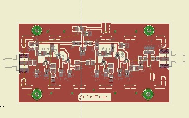
 I did a circuit board layout for the 2nd IF amplifier and quickly etched a board. Everything is surface mount on the top of the board with the bottom of the board kept solid for shielding. Since I plan on shielding all the RF circuitry, I added solder pad areas to the top of the board to make it easier to solder, and also help with the alignment of the shield pieces. My favorite material for making shields is .020" double sided circuit board. It is easy to cut with a scissors or paper cutter, nice and stiff and easier to solder than copper flashing. Everything except the power connections and some filter capacitors are inside the shielded box. The circuit is the same as Farhan's except I added some added capacitors to the DC power line both inside and outside the shielded box. I also used a variable capacitor to the output filter, but added pads for additional capacitors if they are needed.
 Since my eyeballs and fingers do not seem to work as well as they used to do, I stuck with 1206 size components but tried sot23 size transistors for the first time. Unfortunately I only had the correct value for several resistors in 805 size, so I had to use them. Since they were connecting to ground on one end I did not have to change the layout. Actually after I got the hang of using paste solder and a hot air gun, it is probably easier and faster than soldering through hole components. After it was done I hooked it up to the Chinese SNA to adjust the output filter. The 60 pf capacitor I used tuned down to 12Mhz. so I did not need to add any capacitance.
  |
| 12 Mhz 2nd IF amplifier response |

After everything was adjusted, I soldered the shield sides on the module. I will add the top when I get ready to put everything in a box. Now I am in the process of laying out the relay switched band-pass filters, that is turning out to be more than a little interesting project. Will keep you informed.
No comments:
Post a Comment