https://www.youtube.com/watch?v=O6AmT1trO60&list=PLaxN7ey82-BnPIbAzacv_PMvACpAd6ZT7
The boards are laid out using the free "expressPCB" software, this is about the easiest to learn PCB software I have found. Since it was made to be layout software for a single board house, it does have some limitations compared to other programs. But, for making simple "toner transfer" boards it is more than adequate.
I have made a few changes to Chuck's procedure for board layout. The main change has been to modify several of the component foot prints that comes with the software, to provide large mounting pads instead of the through hole pads provided.
 I find it much easier to grab the correct Muppet component from the custom list and place them where I want. These have a outline of the component over the pads, which makes it much easier to follow the circuit diagram. I have pads for the common resistors, capacitors, diodes, transistors, and IC sockets I use most of the time. Any other can be built from standard pads as required. This also makes it easy to mix through hole components along with standard size SMD components if I am laying out a SMD board.
Since the "Muppet" board is etched on the top layer of the PCB, it is necessary to flip the image right to left for proper transfer. Chuck prints the top layer image to a PDF and then uses a linux program to flip it. I found another program "Copper Connection" that will import expressPCB files and then print both sides in the correct orientation for "toner transfer" or photographic method. It also has some nice features that I sometime use to help with the board layout. One of them is to flip a board over when doing double sided boards. Unfortunately it is now hard to find a copy of this software after they were bought out by expressPCB.
Another change is the "toner transfer" method I use. Chuck goes through a great explanation of the "Hot" method using a laminator. I have found that the results of this method is very dependent on the brand of printer used and if you use OEM or generic replacement toner. After seeing another method on a internet site, I switched over to the "Cold" method. This uses a chemical solution to soften the toner, and then the image is pressed onto the blank circuit board. I found that I can get much more consistent results using this method, than I could with the "Hot" method. I have slightly changed this by passing the board and image through my laminator without first waiting for it to warm up. This seems to give more even adhesion of the toner than just pressure alone. I usually pass the board and image through the laminator from several directions to give even adhesion. This works much better for larger and double sided boards. I have a blog entry that describes my method and another later one that covers how I make double sided boards.
https://kv4qb.blogspot.com/2016/01/cold-toner-transfer-circuit-baords.html
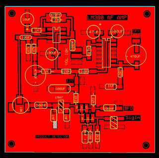
After completing the layout for the LM380 audio amplifier and the product detector, I decided to combine them into a single board. I found that I could open one of the files in expressPCB software, highlight the area I wanted to copy and copy to the clipbaord. Then open the second file and paste the first into it. Then I used the software to reposition components or
add/delete traces as necessary.
Last evening I also finished up
the SMD version layout in two different size formats.
I have a SMD board ready to etch, and hopefully I will be able to get that done tomorrow.
Update 9/4/17
Well I etched the board, and of course I found an error I had caused when I rotated a section of the board around. I made some quick changes, and etched another one. Then built the AF amplifier half of the board, so I can test it without having to worry about any noise or issues introduced by the product detector circuit. Very pleased with the way it turned out. Since I had coated the board with a thin coat of lacquer after I etched it, the only problem I had was trying to get a good picture without a lot of glare off of the board.
I hope to get time tomorrow to do some testing on the amplifier and check what the frequency response is, and how much gain I get out of it.


Are the links to these boards still available somewhere?
ReplyDeleteThe links are in the previous post on the simplecewiver
ReplyDeletehttps://www.dropbox.com/sh/dnfrinb62q1djob/AADtKt96CBMoh9ZQjPqG3u0Ua?dl=0
Sorry, I tried that and it gave me a 404 but this link worked perfectly...
ReplyDeleteHi fellas,
ReplyDeleteThank you so much for this wonderful article really!
If someone want to read more about that Express PCB I think this is the right place for you!
Hi fellas,
ReplyDeleteThank you so much for this wonderful article really!
If someone want to read more about that Express PCB I think this is the right place for you!