Monday, October 26, 2015

Power meter and reference finished.

I finished up the AD8307 power meter and -10dBm reference. 

For the reference I soldered some .020 in double sided circuit board material around the outside edges to protect the components.  Since this will not be used very often I decided to not put in a switch, I just glued the assembly to a 9V battery holder.
I have a new circuit board layout with room for mounting holes that I will build for use as an internal reference in the Spectrum Analyzer I am working on.

After a little cutting and a lot of sanding and touch up work I painted and printed some decals for the Altoids tin I used to house the Power meter.

According to the readings on my oscilloscope the reference should be within 1 dBm of the desired -10 dBm.  After setting the calibration values in the Arduino sketch for the power meter, the readings are consistently within .5dBm.  Checking linearity with several in-line attenuators all readings were within 1dBm.

Without access to other calibrated standards, this is about as accurate as I can come up with, and should be accurate enough for checking most things an amateur would build. 
Now to get back to the spectrum analyzer build.


Sunday, October 18, 2015

20 Mhz. power Reference & Calibrating the Ad8307 power meter

I had the AD8307 power meter working, and compared it against the Chinese SNA in watt meter mode.  The SNA has a built in step attenuator, using that I found the linearity to be very good.  Only thing I was not sure of was the accuracy of the calibration on the SNA.
Looking around the web I found several articles on using a CMOS crystal oscillator can and adjusting for a certain DC output level.  I really wanted something that I could just build and not have to worry about adjusting.  I  would also like to use one as an internal reference for the spectrum analyzer I am building.

 I found a circuit from W1GHZ that looked like it would do nicely. 

http://www.w1ghz.org/small_proj/small_proj.htm 

His circuit uses a crystal oscillator and then takes its output and feeds a pair of back to back diodes.  This should give a very accurate and stable output signal.  This is fed through a low pass filter to remove harmonics of the square wave to a attenuator to set the final output level at -10 dBm.


Looking around I found a 20 Mhz. oscillator that I had form another project.  I used ELSIE to design a 5 pole low pass filter using component values I had on hand.  A small circuit board was built using mostly surface mount components except for the two molded RF chokes in the low pass filter.  I made room on the board so I could parallel resistors and capacitors to make the values needed.  Checking the output level on my scope I fund the output to be around 208 mv. p-p  Close enough the the 200 mv. value for -10 dBm.

The method I used to compute dBm. from the ADC reading on the Arduino does not have a calibration routine.  The correct value has to be determined by trial and error, and entered into the sketch.

While I was trying to find the correct value I noticed something interesting.  When I had the AD8307 meter powered by a battery the reading was very constant. 


 But, when I powered it from the PC when I was uploading the sketch with a different cal value the reading jumped around quite a bit, and was much higher.  Indicating that a lot of noise was coupled from the PC to the power meter.  Having the battery connected at the same time greatly reduced the noise but did not eliminate it completely.  
This indicates that any test instrument powered from the PC might be the cause of noise found during testing.  Powering from battery if possible would probably be the better choice.

It only took me 3 tries at setting the calibration value to get the AD8307 meter to read within 0.1 dBm. of the -10 dBm reference signal.  Now I still need to cut up another Altoids tin to put the meter in.


Friday, October 16, 2015

An AD8307 power meter

When I started on the SPECAN spectrum analyzer, I purchased several AD8307 log detectors.
I found several slightly different designs for power meters, but most are basically the same with different output circuitry.  I decided to stay with the circuit used by Farhan in his Sweeperino and Specan.  Only change I made was to use 33uf molded RF chokes instead of resistors to feed the +5v and bring the  output from the detector to the outside of the shielded compartment.
After deciding on that I took a look at the Arduino software used to read the log detector and convert to dB.  There are several different methods used, some very simple and others that require rather complicated calibration schemes.  

The best way  to test these would be to build a simple power meter.  I had the layout for the power meter part of the SPECAM and the Arduino and display that I had done for the Dummy Load Wattmeter.   Removing the dummy load portion of that board I was able to import the AD8307 power meter circuitry with only a little change  in the original layout.  For the Arduino Nano and Pro-Mini projects I use low profile IC sockets.  Since I want to move to more surface mount designs.  I changed the board layout to have solder pads for the Arduino and display sockets instead of using through hole. 

I etched up a double sided board, with the bottom being solid except for an isoleted block under the AD8307 circuitry.  I had a little problem and the board was over etched, with a lot of pin holes in the ground plane area on both sides.  I flowed a layer of solder over the board to cover some of them.  After populating the board, I cut a .25" wide strip of .020" circuit board material to use as a shield around the log detector circuitry.


I was able to use much of the software from the DL Wattmeter.
I tried several of the chunks of code for the AD8307 interface, and finally went back to Farhan's basic code.  It is one of the simplest and gives results that will be more than adequate for most amateur use.  It does not have a calibration routine, so a cal value has to  be put into the source code.  After only a couple tries comparing the readings with that of the wattmeter function in the Chinese SNA I found a cal value that gave readings within 1 dB of the SNA.

I wrote the software to include the numerical value from the log detector and also have a analog bar display.   I find that a bar display is often easier to use when aligning equipment.  I also added a little code to give another bar showing the peak value measured.  By implementing a counter in the main loop I was able to have the peak reset to the current level after 10 seconds from the last highest peak reading.      Next to put it in another Altoids tin. 

Looking around for a way to check the calibration, I found a simple RF power reference circuit on the web site of W1GHZ.  I had room on the same board as the power meter, so added that layout.  Will update after I finish building and test it. 

Added link to dropbox folder containing the Arduino Sketch, Eagle cad file ,toner transfer image, and parts layout for boards.  

https://www.dropbox.com/sh/ooubfjxdvjao8by/AABe6N-vTZjaMSgUAG0jeGSca?dl=0


Thursday, October 1, 2015

SNA jr Re-build Updated 11/9/2015

There is a upcoming 'Makers Fair' in Atlanta, and several of the local Ham Radio clubs are going to have a display there.  They will demo some equipment and modes of operation. There will also be  several hand's on activities for the attendees. 
I decided to rebuild the SNA Jr. as part of the exhibit. I redesigned the circuit board, making it a little larger to make it easier to build.  Being larger it will no longer fit in the Altoids tin, but I found a metal Crayola Crayon box that was the right size.
 
I also found a nice small 12 V battery pack with charger on e-bay, they are available in several amp hour ratings.  It is just the right size to fit under the circuit board.  It has a built in On/Off switch and  a separate cable with the charging connector, which makes it very easy to build into projects that are battery powered.

Since this will be a show and tell event, I needed to make it "pretty".  Cutting the required holes in the lid of the tin, caused the metal to deform around the cuts. To make it smooth and sturdier, I glued a piece of .020" circuit board material on top of the lid, and filled in around the edges with some auto body filler. After a paint job, I applied some laser printed decals for labels. I also printed a fake bezel to put around the LCD display.

Along with the new circuit board, I also made a new RLB board that will connect directly to the SNA instead of having to use cables.


Here is a picture of the finished unit with the attached RLB.
It shows a normalized scan of my 80-40 meter  dual band dipole antenna.  Using a RL-SWR table lookup, the  SWR values are the same as when I scan the antenna with my FoxDelta Antenna Analyzer.


I have placed all files  necessary for building
including Eagle files and toner transfer image 
 in the following dropbox 
https://www.dropbox.com/sh/kw7c14euqqi28pn/AABc384tePRDZBoqo6s4YDCRa?dl=0


Monday, September 7, 2015

My SPECAN 2nd IF Amplifier

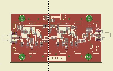
I did a circuit board layout for the 2nd IF amplifier and quickly etched a board.  Everything is surface mount on the top of the board with the bottom of the board kept solid for shielding.  Since I plan on shielding all the RF circuitry, I added solder pad areas to the top of the board to make it easier to solder, and also help with the alignment of the shield pieces.  My favorite material for making shields is .020" double sided circuit board.  It is easy to cut with a scissors or paper cutter, nice and stiff and easier to solder than copper flashing.  Everything except  the power connections and some filter capacitors are inside the shielded box.  The circuit is the same as Farhan's except I added  some  added capacitors to the DC power line both inside and outside the shielded box.  I also used a variable capacitor to the output filter, but added pads for additional capacitors if they are needed.

 Since my eyeballs and fingers do not seem to work as well as they used to do, I stuck with 1206 size components but tried sot23 size transistors for the first time.  Unfortunately I only had the correct value for several resistors in 805 size, so I had to use them.  Since they were connecting to ground on one end I did not have to change the layout.  Actually after I got the hang of using paste solder and a hot air gun, it is probably easier and faster than soldering through hole components.  After it was done I hooked it up to the Chinese SNA to adjust the output filter.  The 60 pf capacitor I used tuned down to 12Mhz. so I did not need to add any capacitance.
12 Mhz 2nd IF amplifier response

After everything was adjusted, I soldered the shield sides on the module.  I will add the top when I get ready to put everything in a box.  Now I am in the process of laying out the relay switched band-pass filters, that is turning out to be more than a little interesting project.  Will keep you informed.


Friday, September 4, 2015

"Canned Frog" finished

I had a bit of a delay in getting the Canned Frog finished when my feline helper decided that the little plastic bags of parts for this and some other projects would make great Kitty Toys.  For several days I kept finding electronics parts spread throughout several rooms, and am still looking for several parts.  After finishing the transceiver board it was time to mount the VFO board and see about putting it in the can.

I soldered a couple small strips of .020" double sided circuit board to the new Arduino VFO board and then to sides of the transceiver board.  Also attached the input filter to the side of the transceiver board.  All in all it made a nice package that fit perfectly into the Armour Treat can. 

One of the biggest problems I have had in the past was how to label the panels. The best luck I have had was with press on lettering, but that limits what you can do and is a pain to get straight.  I thought I would see if the same toner transfer method I used for the boards would work for lettering panels.  I  cut and drilled a front panel from some more .020" circuit board material.  I cut out most of the bottom of the can so I could also make a rear panel from the same material.  Gave them a coat of Gray primer and let dry.

Using  MS-Paint I did up a set of panels and printed them in reverse on the same Hamermill Glossy Color Laser paper  I use for making circuit boards.  A half a dozen passes through the laminator, and a quick soak and the panels came out better than I had hoped.  The lettering looks like it is melted right into the paint.   A couple of heavy coats of Grey Hammer Tone paint on the can and then put it all together

One of the Kitty Toy parts I couldn't find was the final transistor for the transceiver, so I stuck in the closest I had on hand.  Power output was a little low, but I will not worry about that.  The receiver works well except that the audio is fine for phones, but not enough for an un-amplified speaker.

The project accomplished what I wanted.  A small dual output VFO with display that will be the basis for another transceiver some time in the future.


Saturday, August 29, 2015

My version of Farhan's SPECAN

A couple of months ago I started to think about building a simple Spectrum Analyzer.  I thought using a simple Direct Conversion receiver might work for what most hams would need.  Looking around the Web I found a discussion with Ashar Farhan about this approach from a couple of years ago.  I e-mailed him to ask how it had turned out and mentioned some of my ideas of doing simple software image rejection.  He responded and listed some of the problems he had encountered, and gave me  information on the SA he ended up building based on theW7ZOI/K7TAU articles from QST.  Later he gave me a link to the blog entry he was working on discussing the project build, but asked me not to mention until he had finalized it. Earlier this week he finished the article and posed the link.
   http://hfsignals.blogspot.in/p/specan-reboot-of-w7zoi.html

 This is an updated version of the W7ZOI/K7TAU S.A. replacing the vco with a si570 and the control and Scope interface replaced with an Arduino and a serial interface to a PC.  There is a corresponding piece of software on the PC that send control information to the S.A and receives and displays the acquired data.


I decided to build a stand alone S.A. based on this design.  I had been playing with different TFT displays for use in expanding the SNA Jr.  The one I liked most was a 3.2" 320x480 display, it is a nice large display that is designed for use with an Arduino Mega.

Using the Mega, it has a 16 bit parallel interface which is much faster than SPI that the others I had tried used.  I modified the design I had for a interface board to give the needed control and data lines needed for the S.A., also included some others for possible use in other projects.


Spectrum Analyzer Arduino Interface board
Did a quick board layout in Eagle and etched up a board so I could test the display.  I found that the display only needs the pins on the end connector and a connection to the RESET line on the Arduino.
This made layout easier than I thought it would be. and the board a little smaller. I did up a quick sketch to test the board with the appropriate drivers, and was pleased with the result.  Display is nice and large, and has more than adequate resolution for what I want to do. Since the driver graphic primitives are different and more limited than the ones I had used in the SNA jr. it is taking a while to port the software over to the new hardware.

  Since I already have the SNA jr and the Chinese SNA I can get to working on some of the S.A. boards.  The first board, was one I had already started on for expanding the SNA jr.  This was a detector board based on the ad8307, and is nearly the same as the W7ZOI board used in the PHSNA. Only change is that I had a bunch of 7805 regulators on hand and used that instead of a 78L05 , and used a buffer amplifier on the interface board. Later added a shield made from thin double sided PCB material around the detector part of  the board.


Now to lay out  and build some of the other S.A. boards.