Wednesday, August 10, 2022

Farhans' DAYLIGHT Radio

 Unfortunatly I was not able to make it to FDIM this year, but was able to watch the streamed presentations.  All of themwere good, but the one tht interested me the most was Farhans' DAYLIGHT RADIO.  The design is interesting because the input and ouput impedances of the different stages were not all designed to be at 50 ohms. This can make the design a little easier in some cases.

Farhans' design is for an all analog system including the VFO.  Not sure if I will go that way or use a micro-controller and a SI 5351 instead.  There are some ideas  I want to try that would require the micro-controller.  But if everything is in modules, they can be swapped out with the analog stages as desired.  If I went with the Analog VFO I still have enough parts to use one of the small frequency counter boards I built up years ago.

http://kv4qb.blogspot.com/2015/03/dl4yhf-frequency-counter-re-package.html

Farhan resently uploaded a hard-copy of his presentation to his  web site.  https://www.vu2ese.com/index.php/2022/08/04/daylight-an-all-analog-radio/  This has a lot of good information about some of the considerations that went into the design.

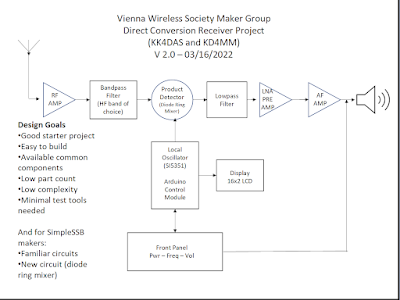
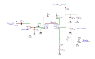
Lets start with the AF Filter and amplifier.  Farhan has a nice desription in his presentation so I will just ashow his schematic. Everything is the same except I am using  seperate opamps for the AF amplifier, and the product detector.  Because of this I  shorted the unused opamp  + input  to the common reference used by the AF amplifier, and the - input to the output . This is left to float,  and as just a precaution to prevent any possible instability of the unused opamp from affecting the AF amp.


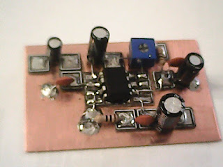
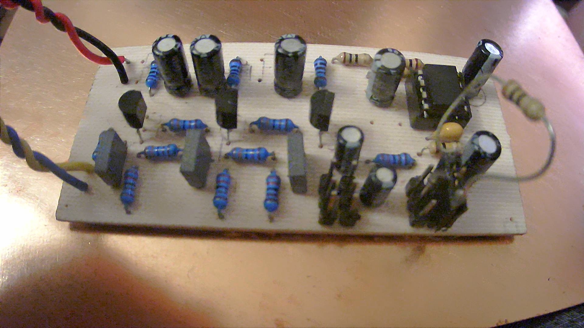
I laid out the board using through hole components, but I might make another using MUPPET style, or shrink it down even more and use SMD components.

I will etch the board using Toner Transfer, but since I also have a CNC I can use it to pre-drill all the holes.  Then it is very quick to align the toner image to the board using the holes as s guide.  This makes the whole process very quick and easy. 

Since the board is fairly siimple I decided not to bother with doing a silk-screen . If wanted I could just print  it on a laser printer, and iron this on the same way as you apply the toner image for etching.

This board turned out pretty nice, so now I can finish the layout of the product detector and balanced modulator board, and get them built.


With as long as it takes to get some of the  components these days, it is nice to have several home brew projects going. at the same timr.  And speaking of home brew, I have a two gallon batch of beer ready to bottle..  Thats always handy to have on hand when it takes toooooo long for the electronic components to arrive.


VWS DC Receiver Low Noise Amplifier

Getting back to working  on the VWS DC Receiver, I decided to combine the AF mplifier and the low noise amplifier on the same board to cut down on size.  Because I have been thinking about having separate Low Pass filters for SSB and CW, I will put them on another circuit board instead of with the LNA.


To better match the low impedance of the of the Low Pass filter, the LNA uses a common base amplifier feeding a common emitter stage.  To provide power supply decoupling, Q2 and the associated components are commonly called a cpacitance multiplier.  This provides a capacitance value to the input stage of approximatly the value of  C3 times the gain of Q2.

This configuration along with the LM-386 stage has over 90 dB. total gain, therefore a separate gain adjustment is added to prevent possible overload distorton.  


I decided to make the board MUPPET style, instead of using through hole.  To reduce the board size I installed the resistors vertically.  I

etched a board using toner transfer, and dipped it in some 'liquid tin' to provide a better soldering surface than just bare coppper.  One of these days I will try one using the CNC router to see if there is much of a difference in the quality I can get.


Waiting on an assortment of inductors, that seem to be taking forever to get here so I can finish the LowPass filter board.


Monday, March 21, 2022

VWS Direct Conversion Receiver Project

I have been working on several projects, most of them not related to electronics.  The main electronic related one has made me look back on some code I wrote 6 years ago when I first started learing C++  and the Arduino IDE.  Still wonder what I was thinking of, and how did I ever get anything to work.  Looking at some of the code made me think it was written in a write-only languge.  Almost as bad as looking at some of the things written in FORTH.  

I had been following the Vienna Wireless Society makers group and their Simple SSB transceiver.  They finished that with around 10 units up and running. Many built by members that had no building expereience.  I had started to build a version of this, but they had mostly finished with the project when I started joining their Zoom meetings.  I had some ideas of how I would like to change this, and then other things came up that postponed  my doing this.  They just started a new project, to try to get more of their club members into home brewing (electronic kind not liquid kind).  This one is a Direct Conversion Receiver which should be easier for the first time builders.

I am going to try to follow along with their progress, and build each module as they are presented.  Probably make a few changes as they progress to reflect some things I already have on hand.  They have a Zoom meeting about every other week, to present info on the next stage in the project, keep up with build progress, and provide assistance as needed.

This is a fairly conventional DC Receiver. The interesting thing is that they plan on using a home made Diode Ring Double Mixer, instead of  a ADE-1, SBL-1. or an active mixer like the NE602.


Here is the block diagram of the receiver, with each block being built as a separate module. Many of these blocks are similar or the same as used in their SSSB project. so there should be plenty support for the first timers available if needed.  They plan on using an Arduino and SI5351 as the VFO, but one of the members has already built an analog PTO that could be used instead.


Their last Zoom meeting went over the block diagram. And, a gain distrabution diagram to define the gain or loss in each stage to get up to the required overall system gain.  


Then went into the first module to be built. This is a basic LM386 AF amplifier circuit taken directly from the LM386 datasheet.  Nearly the same as used in most  all simple receivers.  The only thing that is slightly different, is a variable resistor in series with the gain determining feed back capacitor. Since almost all of the overall gain is in the AF amplifier stage, this resistor allows you to set the final stage gain to prevent clipping on strong signals with the volume control all the way up.

Most of the modules will be built manhatten style using MePads, but any other type of construction would be fine.  Since this is all at audio frequencies, a ground plane is not necessary and it could easily be built using perf bard.  This would be similar to the final stage of the version in my previous post. 


https://kv4qb.blogspot.com/2021/06/simple-ssb-xcvr-mic-amp-build-d-mp.html


I used some simple  PCB layout  software to position all the parts for easy building either with the pads, or to route or etch a board instead. This allows me to make a smaller bard than just eye-balling the parts placement on  a bare bard.  One thing that I did different from the diagram is swap connections to the plus and minus pins (2,3) on the LM386   That just made layout a little simpler. Since the LM386 has a differential input it will not change operation.

The board turned out very nice.  Not as small as could be done by using proto board, or doing a through hole PCB.  But, was faster than either of those two metnods, and should be fairly easy for the first time builder.  When I get a little time, I will do some testing on the board and see what the actual stage gain is, and how much it can be varried with the resistor.

Should be another group meeting later this week to see how everyone is coming along.  Will keep you updated on the next stage in the project.