Sunday, February 28, 2016

QRP SWR Meter UPDATED 3/14

The North Georgia QRP Club has been selling several small kits for the last few years.
One of them is a simple QRP SWR meter, but the small meters that were originally used are becoming hard to get and much more expensive then when the kit was first offered.
Several members of the group spoke to me about coming up with an updated replacement.


I had the Arduino and display circuit along with software I had used in the DL Power meter and the AD8307 power meter.  Using the board layout from these projects, I added a simple directional coupler and detectors built with a binocular core transformer.  With a slight change in parts placement it is possible to build in an Altoids tin.  Or with the display mounted vertically, it can be built in an aluminum project box.


I split the display area with a digital display of the VSWR value in the top half, and bar graphs with digital display of Forward and Reverse values in the bottom. I later added a warning message that would pop up if the VSWR is greater than 3 to 1.   This picture shows the layout I decided to go with. For initial testing I used a couple of variable resistors to input DC values into the Arduino , so values shown are percent of full scale.


After building the directional coupler and detector circuit I did some playing with the software to get a close approximation of the actual power readings.  Everything seems to be working well down to around 2.5 watts.  Below that SWR value starts to loose accuracy.  I am waiting on some different diodes to see if I can get everything working below that level.  If that does not work, I am thinking of changing the detector  to add a little DC bias to the detector diodes.

Here is a quick video of the meter as my auto tuner matches to my multi band antenna.
Will update when I get the new diodes, or have to change the detector circuit.


I gave the first prototype to a club member that has better test equipment than I for test.
After a few minor changes to the software most of everything looks good, except for power values below about 2 watts.  It looks like this is because of the non linearity of the diodes. used.  Tried different types of diodes, but non linearity remains.
I decided that I would add a diode compensated amplifier to rectify this. I was able to find enough room on the board for the op-amp and associated components.  Initial testing looks like the power readings remain accurate down to about 100mW.  Some more testing is requited, but looks like the design is finalized, now to write documentation and see about getting everything ready to do a sample run of the kit.


Wednesday, February 3, 2016

Cold toner transfer and chemical dangers

After linking my two posts on the Cold Toner Transfer method to 
https://groups.yahoo.com/neo/groups/Homebrew_PCBs
there has been much discussion about the danger of the chemicals involved.
Some of these mentioned the effects of day to day heavy exposure found in some industries.  The amount of chemicals used in this method is minute in comparison.  I still have about a third of the 4oz. bottle of mixture I made up after doing 3 single sided and and 3 double sided boards. 


But .it is always advisable to take precautions when working with any chemical.  Even the most common such as dihydrogen monoxide can be dangerous under the right condition.
Years ago I made a simple air filter that I use when etching boards and soldering. It is very small and can be easily setup next to where-ever I am working.

  I had a broken 12 v brushless fan from an old computer.  I cut out the bottom of a disposable food storage container and glued the fan to the bottom, making sure the fan would draw air in through the container.  I then glued a 9 v battery holder to the side of the fan and wired up a switch.
To the back of the fan I attached two of layers of zeolite air filter material, with a single ply of a two ply paper towel between them.  The filter is just held on by twisted wires through the normal mounting holes in the fan.


Very simple and very low cost.  Only thing I had to buy was the air filter material  about $2.00 ( replacement air filter from a kitty litter box).
I can move it around between the soldering station, etching tank and board prep.


Friday, January 29, 2016

Double sided cold toner transfer experiment

I was very happy with the boards I made using the cold toner transfer method, and wanted to see how it would work for dong two sided boards. 

 
 I had a small board I waned to make that has a full ground plane on one side.  I printed the toner patterns directly in Eagle, making sure to mirror the top side.  The best paper I have found for this is Color Laser Gloss from Hammermill.  It is much thinner than photo paper but has the same glossy surface, and is only about $15.00 for 300 sheets.  


I cut the patterns in  long strips, and trimmed the top pattern so it had about a 1" overhang from the  each side of the toner pattern.  Then using a strong back-light I aligned the two patterns and taped the top pattern to the bottom.  I then stuck a piece of paper in between the two patterns to
protect the bottom pattern while I worked on the top.

Using an eye-dropper I placed a small amount of the solvent on one side of the prepared board blank., and slid it between the patterns. After positioning the blank I applied a few more drops of the solvent on top of the paper and spread it around until I could clearly see the toner pattern through the paper.


When It was positioned where I wanted it I placed a piece of printer paper on top and covered with a piece of blank circuit board.  I applied pressure for about a minute to set the toner in position.  I then removed the blank board and first with the paper still in place I used the back of a fork to burnish the toner pattern.  After a little while the paper began to become more opaque.  Then I removed the piece of printer paper and continued the burnishing with medium pressure.  


 When it looked like all the solvent had evaporated from the paper, I turned it over , removed the piece of paper that had been there to protect the bottom toner pattern.  Carefully lifting the pattern slightly I put a few drops of solvent on the board blank and spread it around until even.  I added a little more solvent to the top of the paper until I could clearly see the pattern.  I processed this side the same way as I had the other.

 I checked the board and everything looked fine.  I found one or two small pinholes in the toner on the large ground plane area that I touched up with a marker.  After etching I drilled a couple of holes in the board to check registration.  The photo shows the same hole as seen from both sides of the board.  The registration was much better than I had ever been able to get using the hot method with a laminator.


Sunday, January 10, 2016

N6QW Simple-Ceiver Audio Amplifier testing

I finished building the audio amplifier stages of the Simple-Ceiver and with a speaker hooked up I got a response when I touched the amplifier input.  That is always a good sign, but I wanted to check to see how quiet the amplifier is and the frequency response of the amplifier.
For checking audio stages my favorite program is Visual Analyzer available at  http://www.sillanumsoft.org/

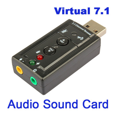
New-Mini-USB-2-0-3D-Virtual-12Mbps-External-7-1-Channel-Audio-Sound-Card-AdapterThis is a PC based software that uses a sound card as the instrument. Not wanting to blow up the sound card in my PC if I do something stupid I use a really cheap USB sound card I got on eBay. This also has the advantage that I can connect it to the computer near my work bench with a USB extender cable, and only have the small unit on the work bench.  I have also used the same card to build a digital mode interface.  The one I usually use is this model and is available for less than $2.00 with shipping.

http://www.ebay.com/itm/New-Mini-USB-2-0-3D-Virtual-12Mbps-External-7-1-Channel-Audio-Sound-Card-Adapter-/161161417325?hash=item2585f8126d:g:2LMAAOSwl8NVVVbp

Visual Analyzer software is a utility package of audio related functions.  It has an oscilloscope, AF Spectrum Analyzer, Signal Generator, Voltmeter, and several other functions I have not used.
With a little additional circuitry it can also be used as a ZRLC meter.


I connected the output of the sound card through a 2.2uF capacitor to the top of the 10 K volume control and the input across a load resistor instead of a speaker.
Setting the sound card to output a 1 kHz sine wave, I adjusted the  output level and gain pot to the point just below where I saw any clipping on the signal.  Then I changed the signal to Pink noise and set the spectrum analyzer to average 100 traces.  This makes a nice clean display of the frequency response of the amplifier.  As shown in the response curve, it is fairly linear to about 12kHz. and then falls off sharply to its low level at around 14.5kHz.
Still waiting for a couple of parts to arrive.  One of them is the 100mH inductor in the output filter of the product detector.  After these arrive I will do a plot of the complete Audio section.


Cold Toner Transfer Circuit Baords

For years I have been using the toner transfer method for making circuit boards.  I have an old Brother printer and a Scotch TL902 laminator that have worked well for this.  One of the problems I have found with this method is that the type of toner you use is very important.  If I use real Brother toner, I get very good results for most of my boards. I have tried using generic toner cartridges that are about 1/3 the price, but have not been able to get very good results.  Another problem is with large ground plane areas, I have  had problems with etch through, and pin-holes showing up in these areas.

I recently saw a post on Instructables about using a chemical method instead of heat to transfer the toner to the circuit board material.
http://www.instructables.com/id/Heatless-cold-Toner-Transfer-for-PCB-Making/?ALLSTEPS


Since my Brother toner cartridge was just about out and I would have to order a new one fairly soon, I decided to give it a try.
Looking around all my painting supplies, for solvents I found a can of denatured alcohol. The original article used Acetone , which I did not have, but I had  some Xylene I had used for thinning and cleaning up some enamel I had painted.  

I printed up several copies of a board I need to etch using the generic toner cartridge.  Playing around with different mixtures of denatured alcohol and Xylene.  I found that a 5 to one 1 mix of alcohol to Xylene would soften the toner without causing it to smear instantly.  I tried the method as shown in the video with fairly good success, and then tried to modify the method a little.  Here is what I came up with.

With an eye-dropper I put enough of the mixture on a cleaned board to evenly cover the board.  Then place the printed paper on the board and moved it around to position it properly on the board. 
After it was positioned on the board, I used the eye-dropper to saturate the paper with more of the mixture.  You could see the paper becoming more transparent and clearly see the toner pattern.
I let this set for about 30 seconds, and then covered with a folded over paper towel.  I then placed another piece of circuit board material on top of the paper towel and applied pressure for about 2 minutes.  After that time I removed the top board, and used the rounded back of a fork to burnish, through the paper towel.  After  it looked like much of the mixture had dried, I removed the paper towel and burnished the laser paper directly.  You could clearly see the toner pattern through the paper.  After a couple of minutes of that, I left everything set for a couple of minutes for the last of the mixture to dry.
After it was dry, I soaked the board in water for a couple of minutes, and removed the paper by lightly rubbing with my fingers.
The toner on the board looked nice and crisp, good adhesion all over, and no sign of smearing.  After etching the board, I found very nice traces, no problems where traces went between IC pins.
Also found nice smooth ground plane areas, with no etch through, or pin-holes.
Looks like I will be able to save a lot of money on toner, and finally retire the laminator.  Probably only used about a half a teaspoon of the mixture, so the remainder of the quart  cans of alcohol and Xylene I had around should last a very long time.

 
Just a couple of pictures of the boards done with this method.
 
The completed board, and a close up showing the sharpness of the etching , and nice solid ground plane area without pin-holes.


Now to get to doing something with these boards.


Thursday, December 31, 2015

The N6QW Simple-Ceiver

I spent most of the holidays visiting relatives. and had quite a bit of time to work on something I had been thinking about doing for a while.  I have been following the development of the Simple-Ceiver that Pete N6QW has been posting on his blog.   N6QW.blogspot.com .  
Pete spends a lot of time going through the design of a DC receiver that is later converted to a single conversion heterodyne  receiver for 40 meters. He goes through the design using LTSpice to simulate each stage before he builds them.  This powerful tool allowed him to optimize the circuit design before melting any solder.
I have a bunch of 12 mHz. crystals left over from the IF amplifier for the Specan, so I could use the same frequency scheme that Pete used.  I plan on using a  version of the SI5351 VFO  I had  built for the "Canned Frog" transceiver.  Different from Pete's circuit I will use another clock output from the SI5351 for the BFO.

 Link to schematic at  https://www.dropbox.com/s/dersy23jgj6h37c/Simple-ceiver-schematic.pdf?dl=0


After drawing the schematic and getting it checked by Pete,  I did a single sided board layout using mostly surface mount components.  I did not have surface mount versions of the ICs for the AF amplifier so I did the layout with extended solder pads for the leaded components. Although I plan on using the SI5351 for the BFO, I decided to add the BFO oscillator to the board.   
Etched the board now to start building and testing the receiver, first the audio amplifier stages.


Friday, December 4, 2015

A PONG Game for Christmas

It is getting close to Christmas, and I need to come up with another present for my son.  He always says that when he was a little kid he had wanted a game system, instead he got a real computer.  He had been a programmer for a while so I guess it wasn't a complete waste.  I think it is time to finally get him a computer game.  Looking around I found a couple versions of the original computer 'PONG"  game for the Arduino. 
I chose  the project from http://michaelteeuw.nl/ 
that looked like it would be easy to port over to the hardware I have on hand.  And of course it would fit in an Altoids tin.
I had an OLED  like the display in my "Canned Frog", but it was two color instead of monochrome.  I had a small TFT display left over from the DL Watt meter project, so decided to use that.

Looking a the schematic, it was very easy to take the board layout from that project and modify it for use for the PONG project.  I was able to remove the Dummy Load and detector components from the board, and move the Arduino Pro Mini and display up towards one end of the board to give room for the two pots I needed for the game controls.  Only other thing was to bring out a pin to connect a small speaker.

After etching the board and installing the components, I started on porting the software to work with the TFT display.  The main advantage of the software I chose, was that it had used the Adafruit graphics library.  I had a compatible library for the TFT display I was using, so it was only took an hour or so to make the necessary changes to use this display.

Main changes was in the resolution of the display, and handling the different colors available to this display.  The OLED display has a clear() function that was used during the draw routine that was not available in the TFT library.  I tried to  replace this with a fillScreen(color) function. Unfortunately this was much too slow and there was a lot of jiter.  Instead of filling the whole screen, I used the fillRectangle(color) function to only clear areas that needed to be redrawn.  This was much faster, and greatly reduced the amount of jitter.  Just a couple of other changes of game play and the porting was finished.
The part of the project that took the longest was cutting and aligning the holes in the Altoids tin.