Monday, September 7, 2015

My SPECAN 2nd IF Amplifier

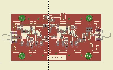
I did a circuit board layout for the 2nd IF amplifier and quickly etched a board.  Everything is surface mount on the top of the board with the bottom of the board kept solid for shielding.  Since I plan on shielding all the RF circuitry, I added solder pad areas to the top of the board to make it easier to solder, and also help with the alignment of the shield pieces.  My favorite material for making shields is .020" double sided circuit board.  It is easy to cut with a scissors or paper cutter, nice and stiff and easier to solder than copper flashing.  Everything except  the power connections and some filter capacitors are inside the shielded box.  The circuit is the same as Farhan's except I added  some  added capacitors to the DC power line both inside and outside the shielded box.  I also used a variable capacitor to the output filter, but added pads for additional capacitors if they are needed.

 Since my eyeballs and fingers do not seem to work as well as they used to do, I stuck with 1206 size components but tried sot23 size transistors for the first time.  Unfortunately I only had the correct value for several resistors in 805 size, so I had to use them.  Since they were connecting to ground on one end I did not have to change the layout.  Actually after I got the hang of using paste solder and a hot air gun, it is probably easier and faster than soldering through hole components.  After it was done I hooked it up to the Chinese SNA to adjust the output filter.  The 60 pf capacitor I used tuned down to 12Mhz. so I did not need to add any capacitance.
12 Mhz 2nd IF amplifier response

After everything was adjusted, I soldered the shield sides on the module.  I will add the top when I get ready to put everything in a box.  Now I am in the process of laying out the relay switched band-pass filters, that is turning out to be more than a little interesting project.  Will keep you informed.


Friday, September 4, 2015

"Canned Frog" finished

I had a bit of a delay in getting the Canned Frog finished when my feline helper decided that the little plastic bags of parts for this and some other projects would make great Kitty Toys.  For several days I kept finding electronics parts spread throughout several rooms, and am still looking for several parts.  After finishing the transceiver board it was time to mount the VFO board and see about putting it in the can.

I soldered a couple small strips of .020" double sided circuit board to the new Arduino VFO board and then to sides of the transceiver board.  Also attached the input filter to the side of the transceiver board.  All in all it made a nice package that fit perfectly into the Armour Treat can. 

One of the biggest problems I have had in the past was how to label the panels. The best luck I have had was with press on lettering, but that limits what you can do and is a pain to get straight.  I thought I would see if the same toner transfer method I used for the boards would work for lettering panels.  I  cut and drilled a front panel from some more .020" circuit board material.  I cut out most of the bottom of the can so I could also make a rear panel from the same material.  Gave them a coat of Gray primer and let dry.

Using  MS-Paint I did up a set of panels and printed them in reverse on the same Hamermill Glossy Color Laser paper  I use for making circuit boards.  A half a dozen passes through the laminator, and a quick soak and the panels came out better than I had hoped.  The lettering looks like it is melted right into the paint.   A couple of heavy coats of Grey Hammer Tone paint on the can and then put it all together

One of the Kitty Toy parts I couldn't find was the final transistor for the transceiver, so I stuck in the closest I had on hand.  Power output was a little low, but I will not worry about that.  The receiver works well except that the audio is fine for phones, but not enough for an un-amplified speaker.

The project accomplished what I wanted.  A small dual output VFO with display that will be the basis for another transceiver some time in the future.


Saturday, August 29, 2015

My version of Farhan's SPECAN

A couple of months ago I started to think about building a simple Spectrum Analyzer.  I thought using a simple Direct Conversion receiver might work for what most hams would need.  Looking around the Web I found a discussion with Ashar Farhan about this approach from a couple of years ago.  I e-mailed him to ask how it had turned out and mentioned some of my ideas of doing simple software image rejection.  He responded and listed some of the problems he had encountered, and gave me  information on the SA he ended up building based on theW7ZOI/K7TAU articles from QST.  Later he gave me a link to the blog entry he was working on discussing the project build, but asked me not to mention until he had finalized it. Earlier this week he finished the article and posed the link.
   http://hfsignals.blogspot.in/p/specan-reboot-of-w7zoi.html

 This is an updated version of the W7ZOI/K7TAU S.A. replacing the vco with a si570 and the control and Scope interface replaced with an Arduino and a serial interface to a PC.  There is a corresponding piece of software on the PC that send control information to the S.A and receives and displays the acquired data.


I decided to build a stand alone S.A. based on this design.  I had been playing with different TFT displays for use in expanding the SNA Jr.  The one I liked most was a 3.2" 320x480 display, it is a nice large display that is designed for use with an Arduino Mega.

Using the Mega, it has a 16 bit parallel interface which is much faster than SPI that the others I had tried used.  I modified the design I had for a interface board to give the needed control and data lines needed for the S.A., also included some others for possible use in other projects.


Spectrum Analyzer Arduino Interface board
Did a quick board layout in Eagle and etched up a board so I could test the display.  I found that the display only needs the pins on the end connector and a connection to the RESET line on the Arduino.
This made layout easier than I thought it would be. and the board a little smaller. I did up a quick sketch to test the board with the appropriate drivers, and was pleased with the result.  Display is nice and large, and has more than adequate resolution for what I want to do. Since the driver graphic primitives are different and more limited than the ones I had used in the SNA jr. it is taking a while to port the software over to the new hardware.

  Since I already have the SNA jr and the Chinese SNA I can get to working on some of the S.A. boards.  The first board, was one I had already started on for expanding the SNA jr.  This was a detector board based on the ad8307, and is nearly the same as the W7ZOI board used in the PHSNA. Only change is that I had a bunch of 7805 regulators on hand and used that instead of a 78L05 , and used a buffer amplifier on the interface board. Later added a shield made from thin double sided PCB material around the detector part of  the board.


Now to lay out  and build some of the other S.A. boards.


Tuesday, July 28, 2015

"Canned Frog" part three UPDATED

Now that I had the VFO and controller completed, it was time to start putting the transceiver circuit board together.  This is a very nice double sided board with plated through holes, and good silkscreen on the top for parts placement. I started with the receiver portion, and checked that I had good audio to the headphone jack.

Since I am making this cover the whole 7Mhz band, I had to replace the single crystal input filter with a double tuned band pass filter. I wired this up on a small piece of perf-board, and tack soldered SMA connectors so I could easily connect to the SNA Jr.


    I could have used the Chinese SNA for this, but I decided to go with the SNA Jr.  I like to use the SNA Jr. for quick alignments because it is small and self contained.   Do not have to connect to my computer and run the software on there,
I set the frequency range from 5.5 to 8.5 Mhz.to put 7 Mhz on the center graticule., and set the SWEEP mode to FAST.  This mode is a reoccurring display instead of a one shot like the other SWEEP modes.  Took just a few minutes to adjust both tuned circuits, and the coupling capacitor.  Much faster than other methods I have tried in the past.


Now to put it in the circuit, connect up the VFO signal and see what I get.  After I connected everything I found that the receive level seemed to be a little low, and there was a constant tone on the signal.  I quickly rewired the input filter as a single tuned circuit, and that brought up the signal level.  Tuning across the band, I decided it would be adequate selectivity for normal operation so will leave it as is.  Looking at the values for the input filter, low-pass filter on the transceiver, and low-pass I put on the VFO board it would be no problem converting this to 10 Mhz. operation.  Just different tuning of the input filter and changing frequency settings in the Arduino code.  I had included a couple of extra Arduino pins when I did the circuit board, so could even add a relay and with a little code change make it a 2 band rig.

The other problem I found was the constant tone. Since I was using a separate transmit and receiver oscillator, I found that I was picking up the transmit signal all the time.  A little change to the code to toggle  the transmit  oscillator off  when receiving took care of that.  With the selectabel tuning step size it is easy to cover the whole band, and switch to the smaller step size for smooth fine tuning.  There are virtually no PLL lockup clicks when tuning in the smaller step size. The only time I heard any was when I made large frequency changes, then a quck click or two when the software switched to a different PLL divider setting. The RIT function works well, and since there is no limit to how far you can tune off the transmit frequency, it acts like true split mode.

Sunday, July 26, 2015

" Canned Frog" part two

I have been working on the circuit board layout for the "Frog Sounds" transceiver, in a "SPAM" can.
Everything fits on a board that just slides inside the can, and will be soldered to the transceiver circuit board. Using the small OLED display along with the Adafruit SI5351 board made this much easier, as they both use I2C for control.  This simplifies the hardware design and makes circuit board layout much simpler.  I was able to find Arduino code for a very simple CW keyer, and added the few required pins and provisions for a keying transistor to the hardware.
The transceiver uses a SA612 in a Direct Conversion receiver, and takes the 612 oscillator output to drive the transmitter.  Since the SI5351 puts out a square wave, I added low-pass filters to the output of the two clock signals I am using. Using Elsie I modeled the filters, and played around with values  so I could use components I had on hand.  Also added provision for attenuators to bring the signals down to the 200-300 mv. that the SA612 wants, also just used values I had on hand .


Everything fit on the board quite easily, except I had to stack the SI5351 board over the Arduino Nano board.  Using a cut down low-profile 40 pin socket, and trimming the pins on the Nano I was just able to get the clearance I needed.   If I wanted to solder the Nano directly to the board, this would not be a problem.
I put right angled pins on the back of the board to allow for easy connections to the transceiver board.


I was able to use  the software I had previously written for a simple VFO, with very little changes.  Since this is a CW transceiver, I limited the tuning rate to either 50 Hz. or 1 Khz.   I am generating  separate Receiver and Transmit VFO signals, so the RIT function is really  SPLIT frequency.  It just starts at the Transmit frequency when switched on.

 The OLED display is actually a monochrome display, with two different colored areas. I decided to use the larger blue area for frequency display, and the smaller yellow area for a status line.

When RIT is turned off there is only a single frequency displayed,  In RIT mode there are two frequencies, the top is the transmit frequency and the bottom is the receive frequency.  When in RIT the tuning rate is limited to 50 Hz. In either case the receive frequency is always shifted down the side-tone frequency.
Control is very simple, a short push on the encoder button toggles RIT on or off.  A long push (1 second) toggles the step size between 50 Hz. and I Khz.  After step size change RIT is turned off.


The only other function is changing the Keyer speed, this is done by pushing in the encoder button and turning the encoder.  If you need a TUNE  for an antenna tuner , setting the Keyer speed to 0 sets the Dit time to 5 seconds and the Dash time to 15 seconds.  This adds a couple of steps when 'tuning up', but simplifies the code a lot.

I also measure the supply voltage about every two minutes, and display this on the status line.  Other status line items are the Keyer speed and the step increment .


Now onto building a front end band-pass filter and making a few mods to the transceiver board. Then stuffing it all in the can.


Tuesday, July 7, 2015

"Frog Sounds" meets si5351 meets SPAM can

I have been following Pete's (N6QW) LBS version 2 transceiver progress, and decided to put my BITX project on hold until he gets his finished.   I might just change over to some of his design instead of what I had been thinking of doing

A while ago I had purchased a small 40 Meter transceiver kit from e-bay.  This is a crystal controlled direct conversion transceiver.


Frog Sounds Radio QRP Kit Telegraph CW Transceiver Receiver Radio Station V3


I was able to listen to the streaming of some of the speakers at FDIM and one of the things mentioned was converting this transceiver from crystal control to a VFO, thought I might as well give it a try myself.
I had done a VFO using an Adafruit SI5351 break out board, and decided this would work well for this project. Looking at the schematic of the board, it uses a SA612 as a crystal oscillator, and has a simple circuit to shift the frequency when going form transmit to receive.  I will use two of the clock outputs of the si5351 instead of shifting the frequency in software when changing from R to T.  This will also make it easier to implement RIT or Split operation. 
Looking around for some Arduino CW keyer code.  I think I might be able to use some of the add on code developed for the TenTec Rebel.
I bread boarded a quick Arduino, SI5351, OLED display to see how it would work.  Most of the code from my earlier VFO ported over to use the new display with very little effort.


Looking at the size of the board, it looks like the ideal project to stick in a" SPAM" can.  Actually a " ARMOUR TREAT" can, it is much sturdier steel than the aluminum "SPAM" can. Just started laying out a circuit board for the VFO front panel, and working on adding to the software.


Will keep you informed.

Tuesday, June 16, 2015

SNA Jr Software update two

I changed the display from a 1.44" 128x128  TFT ti a 1.8" 160.x128 TFT.  Unfortunately they use different driver chips so I had to make some changes to the software , mainly a different driver library and the position of text on the screen.  While I was doing that I also added a couple of
functions to the system.

New circuit board layout moved parts around to make room for the larger display, and added a ERA-3 MMIC amplifier  with attenuator to boost output and present 50 ohm to the DUT. 


After I got the hardware working with the pickup coil to use the SNA Jr. as a Dip Meter, I decided to add a DIP function to the software.  It does a sweep from 1 Mhz. to 50 Mhz. with 50 KHz steps, and looks for the deepest dip in the signal from the RLB.  After that sweep it sets the  range  to 1 MHz.  below and above the dip frequency and then  does a normalized sweep of that frequency range.  Much faster than sweeping through in several ranges.

In the existing sweep functions, they are a single sweep triggered by a short push on the encoder button.  After the sweep is started pressing and holding the button down will enter a setup mode, where you can make adjustments to the gain pots for the sweep range you are using if desired.  Because I added the normalizing  function, I had to do a complete  sweep and then display the data.


From comments on  QRP-L,  sometimes a continuous reoccurring sweep would be better. This would be useful for adjusting filters, and other alignment procedures.

I added a FAST sweep function that does sweeps at around 1 second per sweep. To get this rate I had to remove the setup functionality, and only did one reading at each point instead of using multiple readings to reduce noise. In this FAST mode I erase the old data point and draw the new datapoint as it is acquired.

Still waiting on some parts to arrive, before I can finish testing the updated circuit board layout.  After the last local QRP club meeting I was asked about the possibility of making kits available.  Still trying to decide if I want to go this route, or just make the design for boards and software available.  If anyone would be interested in a kit of this project drop me a e-mail at duwayne@kv4qb.us   Depending on the response I will decide which way I will go.