https://www.youtube.com/watch?v=qoLsynwssLI
The video comments had links to the source code and instructions for building the meter. I thought this would make the basis for a nice little meter that could be added to almost any transceiver.
Thinking about what values I would like to display, I came up with three basic items. A S-meter when in receive, and a power output display when in transmit. In transmit, I would also like to have the capability of measuring VSWR. Thinking about the switching functions required for this I will need one control line that monitors transmit/receive, this can come from the PTT or key line in the transceiver. Then I use a second control line to select either power or VSWR when the T/R line is in transmit. Another control line can do the same for the S-meter or some other display when in receive. Since this is based on a VU meter, I will use that for the secondary function in receive. Now looking at the signal lines I need to measure, they are the AGC line for S-meter, audio signal for VU meter. And in transmit, the forward and reverse power levels will take care of power and a computed VSWR reading.
 I can easily get the 4 analog and digital lines I need from my favorite Arduino for embedding in systems, the Pro-mini. I like it because of its smaller size since it does not have the USB interface built in like the Nano. This also means that it takes a little less current than the Nano. Looking at the physical layout of pins on the Pro-mini, I can get 4 digital, and 4 analog pins in a row that I can use for my control and input signals.
I have some pre-made 8 wire cables with a connector, and matching jack that fits the pin spacing on the Pro-mini. And since I only need 4 wires for I2C OLED display, it was easy to solder a short cable directly from the Pro-mini to a 4 pin connector for the display.
I will be able to supply 5 volts to power everything through the programming pins at the end of the Pro-mini. If needed I can build a small board with a 5 v regulator and possibly some filtering, so I can run everything off the 12 volts in the transceiver.
 After everything was wired up, I loaded the VU-Meter sketch and was very happy with the response of the meter. Since the display is basically monochrome, it only takes a 1 kilobyte image file to completely redraw the screen. This allows for a very fast update, and a realistic looking needle movement. The OLED display I had has a two color effect, that is created by two different colors of plastic in its construction. I have ordered several additional displays that have only the blue overlay. Following the procedure mentioned in the original article, I drew a set of the meter faces I would need for the basic functions of the meter.
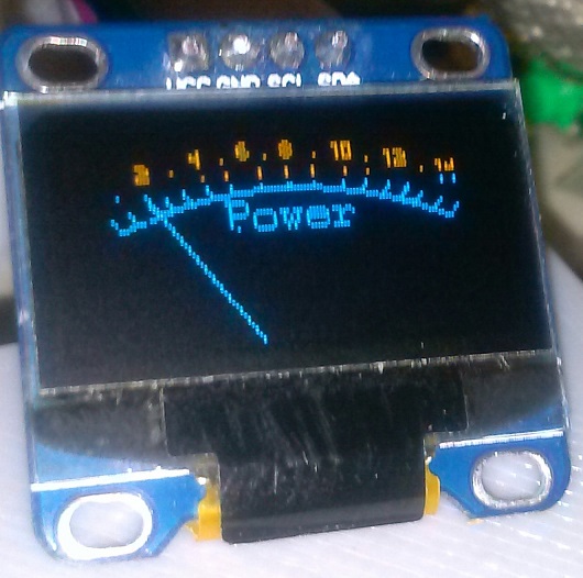


The VSWR display goes up to about 1:3.8 which should be more than adequate for most use. I think I can use the same directional coupler, without its amplifier that I have in my QRP power/SWR meter. Since I am measuring both forward and reverse power, I can compute the VSWR without having to worry about the power output.
As far as the signal levels being measured, I can take anything up to 5 volts without having to add in a adjustment pot or voltage divider. The software should be able to manage full scale and offset values with simple defined constants.
I still have one extra control signal I can use for selecting the display function. Now what else can I do with this display? Possibly an audio frequency spectrum display, so I can join those on 40M with their SDR rigs that are quick to let everyone know exactly how too wide your signal is. Lets see what I can come up with, stay tuned.
UPDATE 4/4/18
Finished up the software to select the desired display screen, and modified one of the Audio spectrum analyzer sketches I found on line to fit in the program space available. It works, but after playing with it, I don't know how useful it would be. With the memory available, it is only possible to do a FFT that will cover to about 5 KHz. , and I would probably have to add a preamp to get enough voltage for a usable display.
 But It works and feeding a fairly large tone in from a signal generator, I could get a reliable display of the spectrum of that tone. Trying it on a normal SSB signal did not give anything I found to be usable. I guess if you were doing CW and had a narrow audio filter in line, you could use the FFT display to see what other signals are around you. Here is a photo of the response with a 1200Hz. signal from a signal generator.
 UPDATE 4/4/27
I spent a little time working on a directional coupler to measure forward and reflected power for the Power/SWR display functions.
I went with the same basic design I had used in my SWR meter, without the amplifier. This should give decent sensitivity with normal output levels on the uBITX.

I need to test it with one of my other transmitters to see what power range I have and if I need to do anything to scale the values before I feed them to the pro-mini ADC.
Here is a link to the software so far if anyone is interested in playing with one of their own.
https://www.dropbox.com/sh/at3ymvlz8sfhefl/AADWlDpcdjlBc2P30TiWva-qa?dl=0