https://www.youtube.com/watch?v=qoLsynwssLI
The video comments had links to the source code and instructions for building the meter. I thought this would make the basis for a nice little meter that could be added to almost any transceiver.
Thinking about what values I would like to display, I came up with three basic items. A S-meter when in receive, and a power output display when in transmit. In transmit, I would also like to have the capability of measuring VSWR. Thinking about the switching functions required for this I will need one control line that monitors transmit/receive, this can come from the PTT or key line in the transceiver. Then I use a second control line to select either power or VSWR when the T/R line is in transmit. Another control line can do the same for the S-meter or some other display when in receive. Since this is based on a VU meter, I will use that for the secondary function in receive. Now looking at the signal lines I need to measure, they are the AGC line for S-meter, audio signal for VU meter. And in transmit, the forward and reverse power levels will take care of power and a computed VSWR reading.
 I can easily get the 4 analog and digital lines I need from my favorite Arduino for embedding in systems, the Pro-mini. I like it because of its smaller size since it does not have the USB interface built in like the Nano. This also means that it takes a little less current than the Nano. Looking at the physical layout of pins on the Pro-mini, I can get 4 digital, and 4 analog pins in a row that I can use for my control and input signals.
I have some pre-made 8 wire cables with a connector, and matching jack that fits the pin spacing on the Pro-mini. And since I only need 4 wires for I2C OLED display, it was easy to solder a short cable directly from the Pro-mini to a 4 pin connector for the display.
I will be able to supply 5 volts to power everything through the programming pins at the end of the Pro-mini. If needed I can build a small board with a 5 v regulator and possibly some filtering, so I can run everything off the 12 volts in the transceiver.
 After everything was wired up, I loaded the VU-Meter sketch and was very happy with the response of the meter. Since the display is basically monochrome, it only takes a 1 kilobyte image file to completely redraw the screen. This allows for a very fast update, and a realistic looking needle movement. The OLED display I had has a two color effect, that is created by two different colors of plastic in its construction. I have ordered several additional displays that have only the blue overlay. Following the procedure mentioned in the original article, I drew a set of the meter faces I would need for the basic functions of the meter.
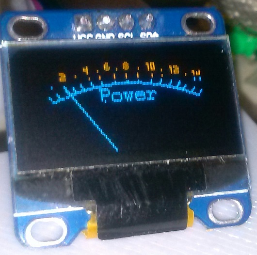


The VSWR display goes up to about 1:3.8 which should be more than adequate for most use. I think I can use the same directional coupler, without its amplifier that I have in my QRP power/SWR meter. Since I am measuring both forward and reverse power, I can compute the VSWR without having to worry about the power output.
As far as the signal levels being measured, I can take anything up to 5 volts without having to add in a adjustment pot or voltage divider. The software should be able to manage full scale and offset values with simple defined constants.
I still have one extra control signal I can use for selecting the display function. Now what else can I do with this display? Possibly an audio frequency spectrum display, so I can join those on 40M with their SDR rigs that are quick to let everyone know exactly how too wide your signal is. Lets see what I can come up with, stay tuned.
UPDATE 4/4/18
Finished up the software to select the desired display screen, and modified one of the Audio spectrum analyzer sketches I found on line to fit in the program space available. It works, but after playing with it, I don't know how useful it would be. With the memory available, it is only possible to do a FFT that will cover to about 5 KHz. , and I would probably have to add a preamp to get enough voltage for a usable display.
 But It works and feeding a fairly large tone in from a signal generator, I could get a reliable display of the spectrum of that tone. Trying it on a normal SSB signal did not give anything I found to be usable. I guess if you were doing CW and had a narrow audio filter in line, you could use the FFT display to see what other signals are around you. Here is a photo of the response with a 1200Hz. signal from a signal generator.
 UPDATE 4/4/27
I spent a little time working on a directional coupler to measure forward and reflected power for the Power/SWR display functions.
I went with the same basic design I had used in my SWR meter, without the amplifier. This should give decent sensitivity with normal output levels on the uBITX.

I need to test it with one of my other transmitters to see what power range I have and if I need to do anything to scale the values before I feed them to the pro-mini ADC.
Here is a link to the software so far if anyone is interested in playing with one of their own.
https://www.dropbox.com/sh/at3ymvlz8sfhefl/AADWlDpcdjlBc2P30TiWva-qa?dl=0
THANKS for info KG7LNA
ReplyDelete'I tried to compile, but no success. I oput the fft h and main into the same Folder, is this correct?
ReplyDeleteWhat error are you getting? I had the fix_fft.h library in the standard Arduino library folder. Try changing #include "fix_fft.h" to #include
ReplyDeletewell, firt I had the fft files in the main folder (whrer oledmeter is) I then put the treef files fix_fft.h. main.c and fix_fft.c in to the library filter (on C). Still i get the following Errors:
ReplyDeleteC:\Users\Henning\AppData\Local\Temp\ccHyC32d.ltrans0.ltrans.o: In function `main':
sketch/main.c:17: undefined reference to `fopen'
sketch/main.c:22: undefined reference to `fseek'
sketch/main.c:23: undefined reference to `ftell'
sketch/main.c:24: undefined reference to `rewind'
sketch/main.c:32: undefined reference to `fopen'
collect2.exe: error: ld returned 1 exit status
exit status 1
Fehler beim Kompilieren für das Board Arduino Nano.
BTW: under which folder in the library filder on drive C do I have ot pack the fft files and how to Name this folder?
Where did you get the main.c file? Errors are from there, and there should not be a main.c anywhere in the sketch.
ReplyDeleteDuwayne, well i was a bit pussled, 'IO gooled for fix_fft, and presumably got the wrong files, not the lib file for Arduino. By exchanging this I am able to compile errorless. 18310 Bytes (59%) is the result.
DeleteI guess tha thte selecttion of the Input (A0 to A3) is done by D10 to D13, correct?
But to which pin must I put SDA and SCL (I2C) of th Nano to the display?
A schematic would be helpfull even for othe rreaders.
I am still waiting on my Displays to come from CHina. BTW: the 0.96´´ Display are chap, the 1.3´´ are expensive. Any Explanation for this?
Glad you got everything to compile. There are several different versions of the pro-mini and the display that have the I2C pins ( arduino A4 A5)located in different places, so a drawing might be confusing. All the boards I have had them marked so just connect what you have to labeled pins on the display. Pricing is probably because of quantity demand for each part, and I have seen the .96" parts around longer.
ReplyDeleteDuwanyne, i just got the 0.96´´ Display (blue and yellow colour) and after sucessfully compiling and loading it into my Arduino Nano using the Nano´s 5 V supply and pin 28 = SCL pin 27 = SDA I have success, the Smeter is shown. Connecting 3,3 V to A0 pin 23 i get the needle to S9. Fine! But how can I Change the dispaly to the other modes? Putting 3.3 V tro pin 10, 11 12 and 13 (PD6, 7, PB0,1) no change. On these pins only 0,29 V is there, but Pins 14, 15 and 16 I measure 4,2 V. Connecting 14 to gnd I get power, 15 to gnd does not change anything, 16 to gnd I get VU, but where can i Change to fft?
ReplyDeleteDigital control pins are defined as shown below. They are inputs with pullup resistors enabled., to set default modes if nothing is connected To change selection you have to ground the appropriate pin. Transmit/receive mode select can be connected to the PTT line.. Then a switch for the transmit mode select and another for the receive mode select.
ReplyDelete#define RecXmt_select 10 // receive transmit select
#define Xmt_Mode_select 11 // transmit disp select power or swr
#define Rec_Mode_select 12 // receive disp select s-meter or vu meter
#define Alt_Mode_select 13 // alternate display mode select
This comment has been removed by the author.
ReplyDeleteVery nice, I want to do it.
ReplyDeleteUnfortunately, my Google translator English () leaves me in doubt ... This project has input lines that, depending on which one is activated, the display shows one value or another, right? If so I will do it for my uBitx. Thanks
Nice! The creativity and drive to "make something that did not exist" is lovely. Well done!
ReplyDelete